Do you have a question about the Lifan KP4500iE and is the answer not in the manual?
Explains the meaning of DANGER, WARNING, and NOTICE headers used in the manual to indicate potential hazards.
Details important safety specifications, including operational do's and don'ts illustrated with pictograms.
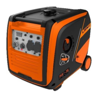
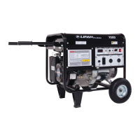
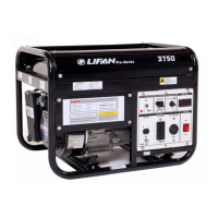
Identifies and labels the main external parts of the generator, such as the handle, fuel cap, and control panel.
Explains the function of the low oil warning light and its indication for insufficient oil levels.
Describes the red overload indicator light, its causes, and the protection mechanisms activated.
Explains the green AC indicator light, signifying stable output operation.
Details the ECO switch function for controlling engine speed based on load for fuel efficiency.
Explains the purpose of the ground/earth terminal for preventing electric shock.
Describes the AC breaker protector's role in stopping the generator during short circuits or overloads.
Provides crucial safety instructions and guidelines for refueling the generator with appropriate fuel.
Details the critical safety precautions and requirements for connecting the generator to a home or mains electrical system.
Explains the necessity and method of grounding the generator to prevent electric shock and appliance damage.
Provides guidelines for connecting AC power, emphasizing load limits and connection order for multiple devices.
Discusses load types, their starting current requirements, and provides a table for reference when connecting appliances.
Explains potential performance adjustments needed for operating the generator at altitudes above 1000m.
Provides step-by-step instructions for starting the generator using the recoil starter mechanism.
Outlines the procedure for starting the generator using the electric start function, involving battery connection.
Explains how to use an external DC12v power supply or battery to start the generator when the internal battery is depleted.
Presents a detailed maintenance schedule for regular service, including intervals for engine oil, air filter, and spark plug checks.
Offers a troubleshooting guide for diagnosing and resolving issues when the generator engine fails to start.
Provides a troubleshooting guide for diagnosing and resolving issues when the generator produces no voltage output.
Presents the electrical circuit diagram for the generator's recoil start system.
| Brand | Lifan |
|---|---|
| Model | KP4500iE |
| Category | Portable Generator |
| Language | English |