4
Fig. (2)
335
81
170
582
003
22
170
192
5961z
9981z
18
AC003a
7861z
1981z
45
Fig. (3)
XD
XS
Fig. (4)
1
4
350
250
200
3
AC005
2
1
AC010
4
350
250
200
Fig.4.1
Fig.4.2
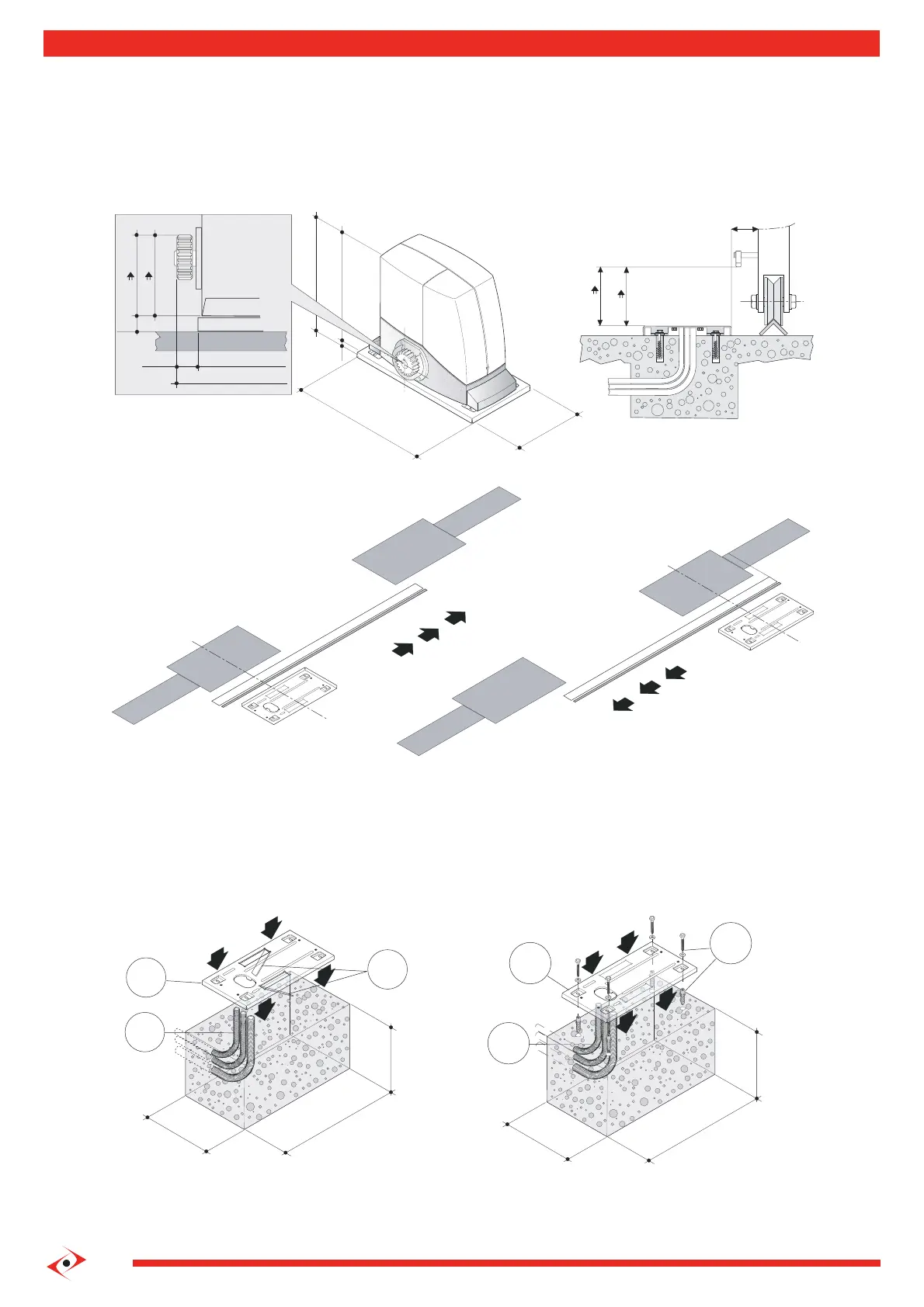
1.2 Installing operator components: positioning and installation of the anchorage plate
The area in which the operator is installed must provide adequate space for performing maintenance
and manual release operations.
a) Adhere to the dimensions in g.2.
Left Hand
Right Hand
ATTENTION: If the operator is subject to heavy work conditions or if the weight of the leaf is over 300 kg,
the anchorage plate (1) must be sunk into the concrete.
b) Observe the orientation in g. (3) for positioning the operator anchorage plate (R – L).
c) Refer to g. (2.2) for the respective heights for 16 or 18-tooth pinions.
d) Lay the electric cable pipes (4), allowing them to protrude and plugging them to prevent them from lling with debris.
Fasten the anchorage plate (1) to the concrete base with 4 expanding screw anchors (2), see g.(4.2); or sink in the fresh
concrete folding the two “L”s (3), see g.(4.1).
 Loading...