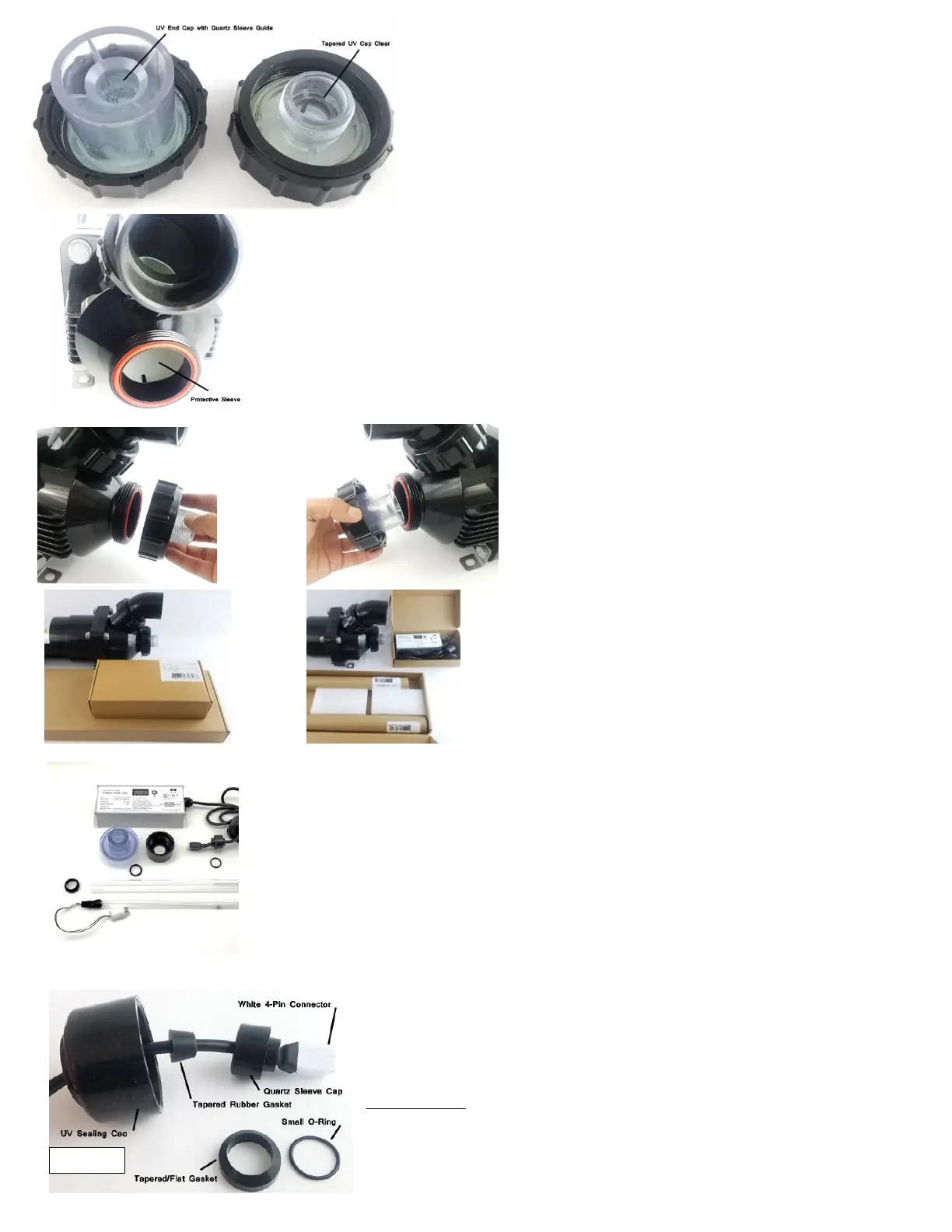
Look at the UV clear cap (#15). It has a tapered hole on the inside of the threads.
The other end of the sterilizer is the UV end cap (#2). It has a hold on that holds the
Quartz sleeve (#14) and acts as the quartz sleeve guide. When you are installing the
quartz sleeve it will sit inside the UV end cap. It makes sure that the quartz sleeve is
perfectly aligned and in the center of the sterilizer.
When you look inside the 2” openings you will notice there is a white protective sleeve (#7, 13) on the inside of
the UV. This is the replaceable sleeve that you need to service once a year to make sure that the UV light
damaged does not extend to the black UV housing. We will cover this again in the service section at the end.
Now put the clear fittings back and hand tighten the nuts and
make sure they close and seal properly.
When you open the UV box you will notice two additional
boxes. The smaller box contains the UV ballast and the larger
box contains the UV bulb (#17) and quartz sleeve (#14).
Please note that the 3” Size UV in 25 watt and 40 watt have a
standard UV bulb and a standard UV ballast. The 3” and 5”
Size UV's in 55 watt, 90 watt and 120 watt have an amalgam
UV bulb and a amalgam UV ballast with a day counter.
Remove the ballast from the box you will see the parts in Figure 2.
The small bag in the UV box containing one O-ring (#19) and a larger tapered/flat
Gasket (#16).
Familiarize yourself with all the parts that come with the Pro Max UV to connect
the Quartz
Sleeve, Quarts Bulb and Ballast to achieve proper seal.
NOTE: The ballast shown in these photos is an Amalgam UV ballast used in 55, 90,
120 Watt UV.
Familiarize yourself to the part and note where the White 4-pin connector of the UV ballast is
located.
From right to left you will see the white 4-pin connector followed by the plastic quartz sleeve
cap (#20) followed by the tapered rubber gasket ‘seal’ (#21) to seal the cable and finally the
UV sealing cap (#22). Figure 3
Install the small O-ring (#19) inside the quartz sleeve cap as shown in the image below. Make
 Loading...