FlexPower Vantage R8 Access Power System - Installation Manual 10
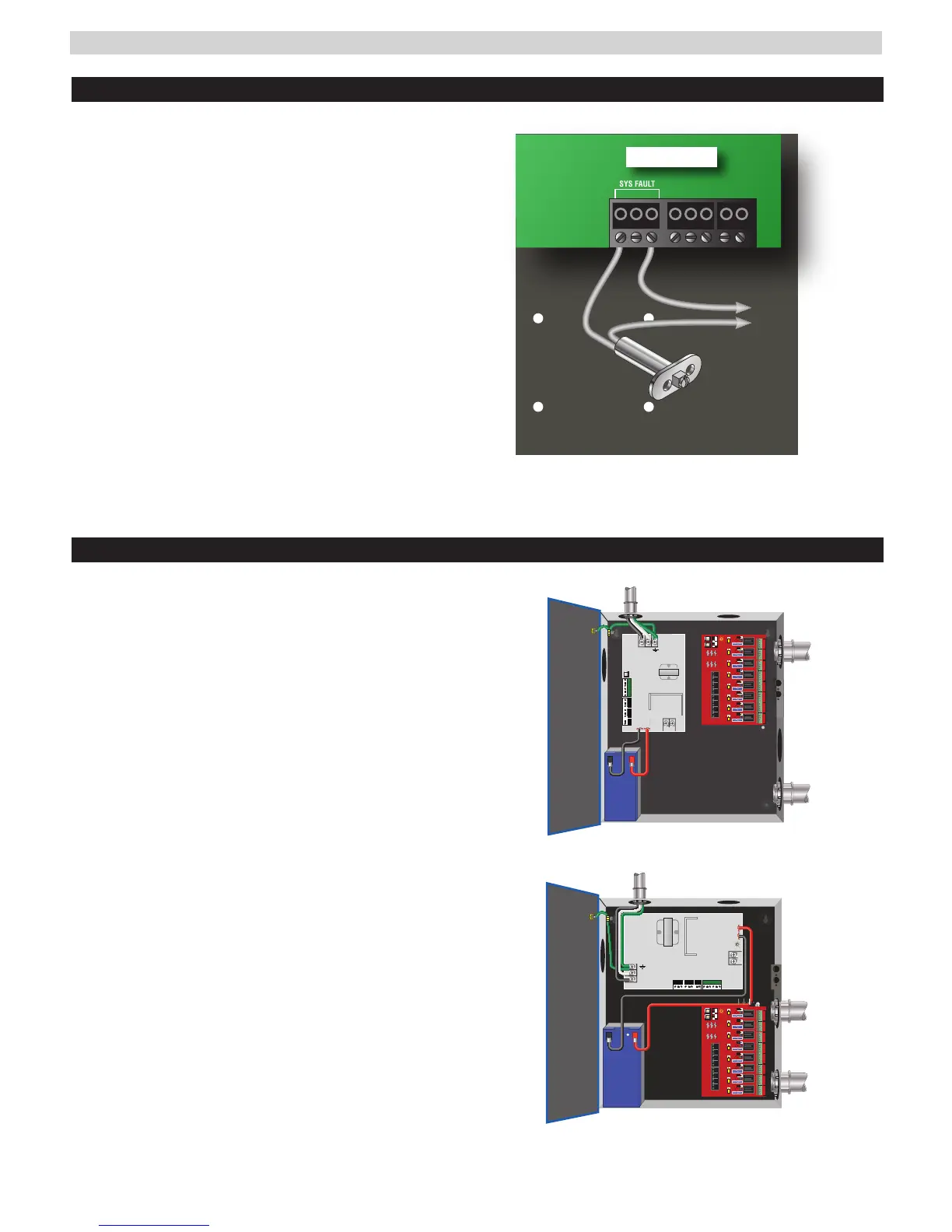
Tamper Switch Wiring
Typical Installation and Wire Routing
Vantage power supply systems with an enclosure may in-
clude a normally closed tamper switch for monitoring by
the host panel.
The tamper switch can either be brought into a dedicated
input in the panel (see the panel's instructions), or the
tamper switch may be series connected into the System
Fault relay in the FPV supply (see Figure 1).
Any UL1076 installation must use the tamper switch to
indicate the opening or removal of the front door of the
enclosure.
SYS FAULT
AC FAULT AUX
C NC NO
Tamper
Switch
Fault Connections
to Panel
FPV Power Supply
FPV6, 102, 104
N
L
BATTERY
AC INPUT
FPV4
BATTERY
NL
AC INPUT
GND GND GND GND
1 2 3 4
GND GND GND GND
5 6 7 8
GND GND GND GND
1 2 3 4
GND GND GND GND
5 6 7 8
NC C N0 COM NC C N0 COM
OUTPUT - 1 OUTPUT - 2
NC C N0 COM NC C N0 COM
OUTPUT - 1 OUTPUT - 2
NC C N0 COM NC C N0 COM
OUTPUT - 1 OUTPUT - 2
NC C N0 COM NC C N0 COM
OUTPUT - 1 OUTPUT - 2
GND GND GND GND
1 2 3 4
GND GND GND GND
5 6 7 8
GND GND GND GND
1 2 3 4
GND GND GND GND
5 6 7 8
NC C N0 COM NC C N0 COM
OUTPUT - 1 OUTPUT - 2
NC C N0 COM NC C N0 COM
OUTPUT - 1 OUTPUT - 2
NC C N0 COM NC C N0 COM
OUTPUT - 1 OUTPUT - 2
NC C N0 COM NC C N0 COM
OUTPUT - 1 OUTPUT - 2
Figure 1 - Tamper switch fault relay wiring
Figure 2 - Wiring
Figure 2 shows a typical installation.
Actual configuration and wire routing will vary based on the
components installed in your system.
The following guidelines should be followed for installation:
• Class 2 Power limited wiring must be separated from non-
power limited wiring by a minimum of 1/4 inch and must
use separate knockouts.
• Any wiring passing through knockouts in the bottom or
top surfaces of the enclosure must be enclosed in rigid or
flexible metal conduit.
• Canadian Installations - For permanently connected
equipment, a readily accessible disconnect device shall be
incorporated external to the equipment. Output circuits
not connected to removable terminal strips shall also uti-
lize a readily accessible disconnect device.
 Loading...