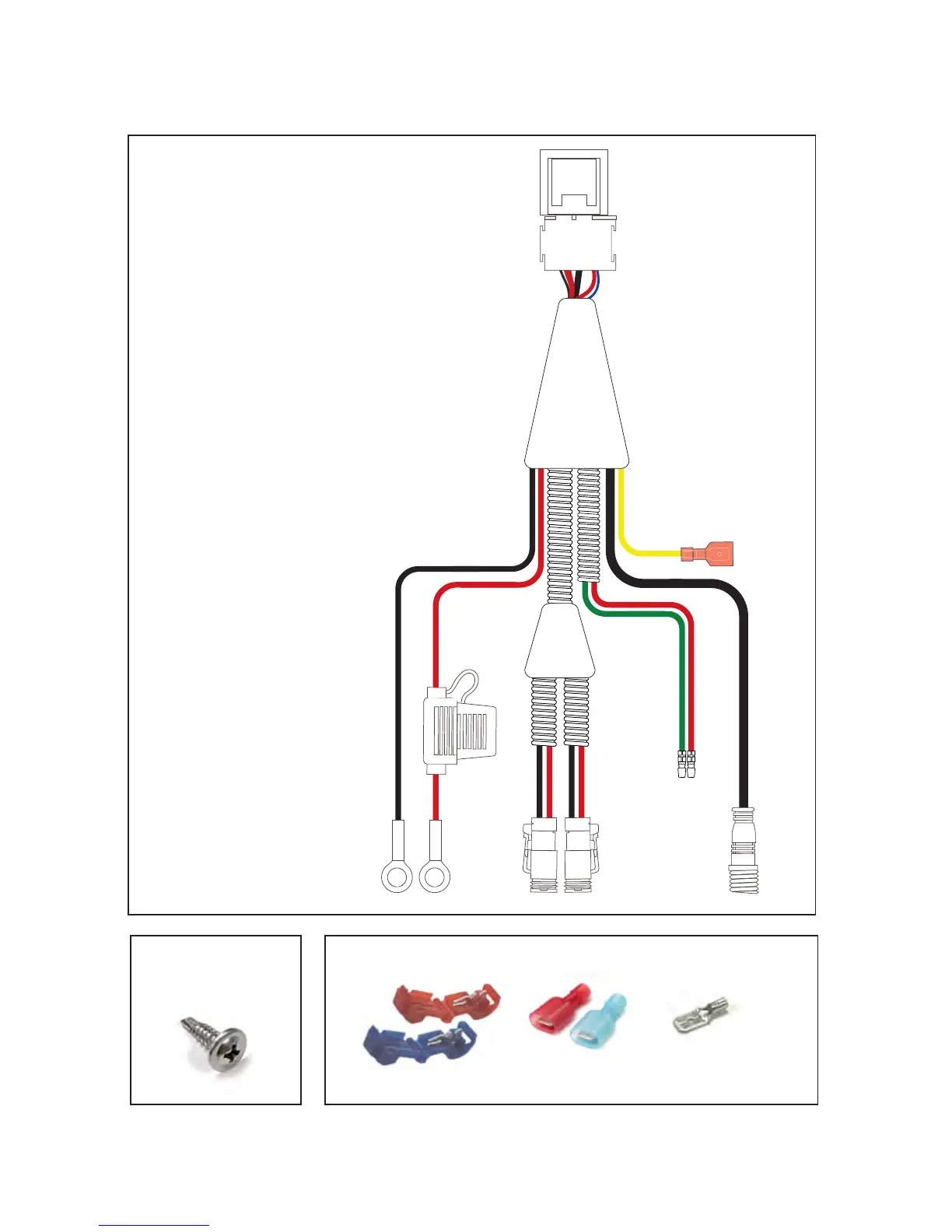
3
STRIKER LED INSTALLATION INSTRUCTIONS
1
3 4
5
6
7 8
9
10
Green Red
Black Red
Yellow
Fig 1. Driving Light Harness
1. 40 amp Relay
2. Insulated sleeved wires
3. Battery connector (negative)
4. Battery connector (positive)
5. 15 amp fuse
6. Driving light connectors
7. High beam pickup wire
with bullet terminal (negative)
8. High beam pickup wire
with bullet terminal (positive)
9. Dashboard switch loom connector
10. Dash illumination cable (optional).
Fig 3. Connectors for non-standard installationsFig 2. Screw
for xing relay
T-taps for wires
Insulated male
spade terminals
Un-insulated male
spade terminal
2