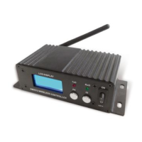
Front board
1:LCD display window 2:Indicator light of transmitting 3:Indicator light of receiver 4: Setting
knob of transmitting power rate 5:ID Option Knob 6:Power Switch
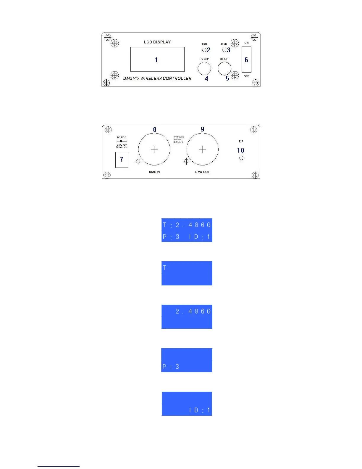
Back board
7: Power supply input jack 8:DMX Input Socket 9:DMX Output Socket 10:RF Antenna
Display describing:
1. LCD display- - - - - - - - - - - - - - - - - - - - Include working condition、RF frequency、
transmitting power rate、ID coding etc.
2. Working condition- - - - - - - - “T”=TXD transmitting ”R”=RXD receiving ”-“ = searching
signal,no setting needed when it works self-moving condition.
3. RF frequency- - - - - - - - - - - - - - - - - - 2. 400-2. 525 G,Total 126 channels,no setting
needed when it works self-moving condition.
4. Transmitting power rate- - - - - - “0”=2dBm “1”=8dBm “2”=14dBm “3”=20dBm,
Press ”PRF UP” for setting
5. ID Coding- - - -“0-F” 16 groups ID coding,press ”ID UP” setting,Same ID can communicate
each other only.