EasyManuals Logo

Lightolier MULTISET PRO MDC20 User Manual

Lightolier MULTISET PRO MDC20
8 pages
To Next Page IconTo Next Page
To Previous Page IconTo Previous Page
Page #7 background imageLoading...
Page #7 background image
Setting the Button Brightness (Ellipse Series)
The brightness level of each Ellipse Master Control Station button can be programmed to 100% (factory default), 75%, 50%, or 25%.
To change the setting:
1. On a 5-Scene Master, press and hold buttons “B” and “D” simultaneously for 3 seconds (on an 8-
Scene Master, press buttons “H” and “J”). On a 5-Scene Master, buttons “A” thru “D” illuminate
(on an 8-Scene Master, buttons “G” thru “J” illuminate). The blinking LED displays the current
LED brightness setting. The continuously-illuminated LEDs display the available brightness set-
tings that can be selected.
2. To change the brightness setting, press the button illuminated at the desired brightness. This button
will begin blinking.
3. To save the selected brightness and exit the mode, press the ON button on a 5-Scene Master (or the
“E” button on an 8-Scene Master). All buttons on that master will now have the new brightness setting.
%001GA
%57HB
%05IC
%52JD
5-Scene
Master
8-Scene
Master
LED
Brightness
7
Connecting Multiple Cabinets
Up to 30 MultiSet Pro® Devices may be controlled as one system.
ABCD
1
2
3
4
5
MHPWDC20
Circuit Breaker Panel
To Lighting Loads
(One dimmed 120VAC Line / Neutral per circuit)
120VAC Line / Neutral
Up to 20 Circuits...
Purple Wire
MDC20
ABCD
1
2
3
4
5
Purple Wire
MHPWDC20
MDC20
ABCD
1
2
3
4
5
MDC20
ABCD
1
2
3
4
5
Figure 13
Figure 14
Figure 15
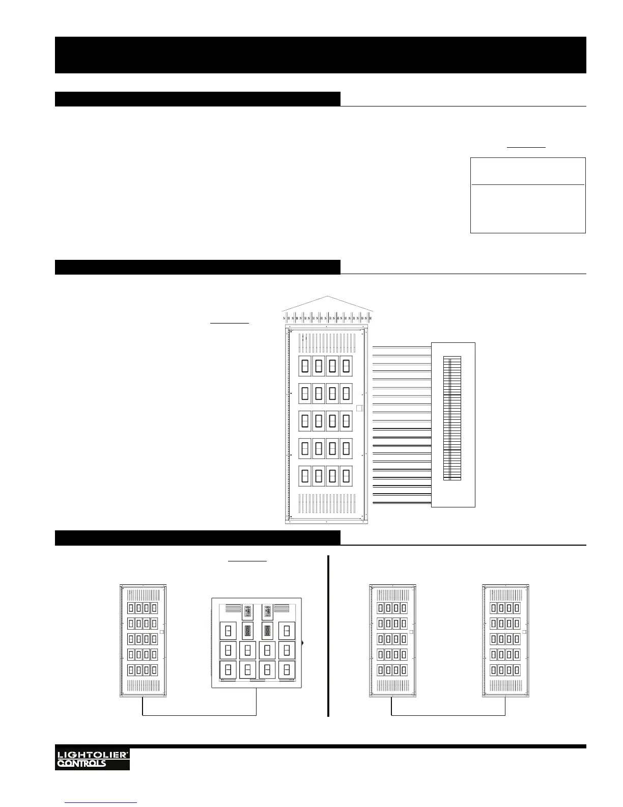
Typical Wiring Diagram
MULTISET PRO
®
- PRE-WIRED DIMMING CABINET MDC20
Installation
and Operation
See Page 3 for Terminal Block
Wiring Descriptions.
Note: No Common Neutrals
on Dimmed Circuits.
Note: Knockouts are provided
on top and both sides.

Questions and Answers:

Question and Answer IconNeed help?

Do you have a question about the Lightolier MULTISET PRO MDC20 and is the answer not in the manual?

Lightolier MULTISET PRO MDC20 Specifications

General IconGeneral
BrandLightolier
ModelMULTISET PRO MDC20
CategoryDimmer
LanguageEnglish