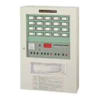
This document describes the AHC-871 Fire Alarm Control Panel manufactured by HORING LIH INDUSTRIAL CO., LTD. It is an advanced, accumulation-type control panel designed for ease of maintenance and aesthetic appeal, meeting most end-user requirements.
Function Description
The AHC-871 is a sophisticated fire alarm control panel that monitors various detectors and manual call points to detect fire and trigger alarms. It provides visual and audible indications of fire, disconnections, and system status. The panel incorporates features to minimize false alarms, automatically reset after tests, and facilitate communication and maintenance.
Key Functions:
- Fire Surveillance: Continuously monitors connected detectors and manual call points. In normal operation, the "AC Power" LED is on, the Voltmeter indicates 24V (20V-28V allowable), and indicating lamps in PBL combination boxes are lit.
- Fire Alarm: When a detector activates or a manual call point is pressed, the "Fire" Indicator (red) and the concerned zone indicator light up simultaneously. The Main Bell and Area Bell sound, and the Indicating Lamp on the Combination PBL box blinks, confirming a valid fire alarm.
- Reset: After a fire alarm, the "Fire" Indicator and related Zone Indicator remain lit. Depressing the "Revert" button resets the system, provided detectors are not burnt and manual call points are recovered.
- Disconnection Alarm: The panel features a "Zone Disconnection Auto Indication" function. A circuit break or detachment of a terminal resistor causes the "Disconnection" LED and the related zone indicator to blink simultaneously, accompanied by a disconnection beeper.
- Fire Alarm Test: Allows for simulation tests, field tests (using a tester near a detector or pressing a manual call point), and control panel self-testing. The system automatically resets after these tests.
- Disconnection Test: Enables testing of disconnection signals by setting the "Test" and "Disconnection Test" switches and depressing the Zone Test button, or by removing a detector.
- Standby Power: Equipped with automatic rechargeable batteries (24VDC) for standby power. In case of main power failure, the "AC Power" LED turns off, the "Battery" LED lights up, and the Voltmeter shows 24V. A "Battery Test" switch allows for testing this function.
- Telephone Communication: Includes a hand-held telephone that can be plugged into a manual call point for communication. The "Telephone Buzzer" sounds, and the "Telephone" Indicator lights up during communication.
- Consecutive Activation of Hydrants: Provides a voltage-free contact (24V/10A) to simultaneously activate Hydrant Activating Devices when a fire alarm is valid.
- "Attention Switch" Indicator: Blinks if any switch on the display board is not in the "up" position, ceasing when all switches are correctly set.
Important Technical Specifications
General:
- Power Source: 220VAC 50/60Hz (Others also available)
- Stand-by Power: 24VDC
- Charging Voltage Current: 26VDC 100mA~400mA (With auto adjustment function)
- Voltage Current: 24VDC short circuit under 5V 30mA
- External Line Resistance: Below 50Ω round trip
- # of Heat Detector Connected: No limit (Except electronic-type)
- # of Smoke Detector Connected: 30/zone (Horing Lih manufactured)
- PBL Combination Panel Wiring: 4 Lines or 6 Lines (Depending on requirements)
- # of Indicating Lamp, Area Bell Connected: # of zone X 1.2
- End of Line Resistor: 10KΩ (One per zone)
- Material: 1.6mm steel
- Color: Ivory-white (Others also available)
Wiring Specifications (for long distance wiring or large control panel):
- Circuit Line: 1.2mm (Quantity N, depends on devices, one line for every zone)
- Common Line: 1.6mm (Quantity N, every common line should not have more than 7 zones)
- Area Bell: 1.6mm (Quantity 2)
- Indicating Lamp: 1.6mm (Quantity 2)
- Manual Call Point: Parallel connection to each zone's detector.
- Telephone: 1.2mm (Quantity 2)
- Transmitter: 1.2mm (Quantity 1)
- Earth: 1.6mm (Quantity 1)
- AC Power: 1.2 to 1.6mm (Quantity 2, depending on the load of the control panel)
Fuses: The panel has six fuses (F1-F6), each with individual protection:
- F1: Alternate power source 24VDC
- F2: AC power source 220VAC
- F3: Stand-by power source
- F4: Extra power source
- F5: Area Bell
- F6: Indicating Lamp in the combination PBL box
Usage Features
Up-to-date Designs:
- Accumulative Capability: Designed to eliminate false alarms caused by pulsative waves and interfering signals, especially with smoke detector loops, minimizing or preventing their occurrence.
- Automatic Reset Capability: The auto reset button performs a Detector Test in addition to normal reset.
- Fuse Fault LEDs: Indicates failures due to faulty wiring or other causes.
- External Indicators: Option for 'light-on' (I) or 'light-off' (O) mode for the Fire Indicating Lamp during power failures. 'Light-off' mode prolongs surveillance by only blinking during a fire.
- Reserve Slot for Relay Output: Optional.
User-Friendly Design:
- Zone Testing Button: Located at the Zone Indicator, it is self-returning and allows for individual zone testing.
- Voltage Stabilizer: Verified with applied sudden voltage loads before delivery.
- Durable Construction: Made of steel-plate with an attractive oven-baked paint.
- Clear Indicators: Every zone indicator has two LEDs in series, covered by a glossy light bulb shield. Removable plates are included for labeling different areas.
- Dust Protection: Zone Testing Button and Relay are tightly sealed to prevent bad connections from dust accumulation.
Installation Considerations:
- Wire Connection Box: Each floor or area should have a water-proof Wire Connection Box with connecting joints, labeled "Fire Fighting Only" on an aluminum plate.
- Wire-Point Labels and Joint Clips: Wire points inside the control panel and connection boxes are attached to Label Covers or Stickers and connected to Y-clips.
- Terminal Resistor Connecting Method: Every end of a Circuit line must have a Resistor (not more than one). If a zone is not in use, set the Dip Switch on the Terminal to "ON".
- Zone Labeling: Provided "Zone Labeling Card" for easy identification after wiring.
- Wiring Record: Detailed external wiring diagrams should be kept for future inspection and repair.
Maintenance Features
Important Notes on Maintenance:
-
Normal State:
- Normal Condition (Fire Surveillance Alert): "AC Power" LED on, Voltmeter at 24V (20V-28V), all switches in "up" position, PBL combination panel indicating lamps lit.
- Power Failure: "AC Power" LED off, "Battery" LED lit, Voltmeter at 24V (20V-28V).
-
Maintenance of Devices:
- Coordinate with the public if maintenance may cause disturbances.
- Prioritize faulty devices.
- Schedule maintenance at least twice a year, including physical and functional inspections.
Overall Maintenance (Yearly):
- Professional Inspection: Carried out by a professional institution or the Original Equipment Manufacturer. Records must be kept.
- Power Supply Check: Verify external wiring, power consumption, standby power conformity to specifications, and duration of power supply.
- Control Panel Check:
- Fire Test: Ensure the fire alarm system functions properly.
- Circuit Break Test: Verify the "Zone Test" button functions properly.
- Detectors Check: Perform site tests to check functionality and the condition of the detector's indicating LED.
- Manual Call Point Check: Inspect plastic plate integrity, press-down button, and wiring condition.
- Insulation Test: Insulation between power terminal and earth should be 250V 20MΩ or above.
Trouble-shooting (Designed for ease of use without special skills):
- Malfunction of Zone Indicator and PBL Combination Panel:
- Measure AC power (should be 220V).
- Check "Normal Power" Switch (ON) and green LED on power board.
- Check "AC Power" Indicator and Voltmeter (should be 24VDC).
- Check fuses (or "AC Power Failure" LED).
- Verify external devices and wiring conform to specifications.
- Functions of Fuse: Do not replace with non-conforming or low-quality fuses. Burnt fuses usually indicate external wiring errors, short circuits, or faulty external devices.
- Stand-by Power Source In Reverse Order: If polarity is reversed, F3 fuse will burn. Correct polarity immediately.
- PBL Combination Panel Indicating Lamp and Area Bell Malfunction:
- Remove external wiring.
- Measure (+) outlet of Indicating Lamp (should read DC24V) and perform fire test for intermittent power.
- Measure (+) outlet of Area Bell (should have no voltage normally, then 24VDC during fire test).
- If tests conform, panel is functioning; repair external wiring before reconnecting.
- Zone Indicator Malfunction: 90% due to incorrect external wiring, other factors include incorrect handling or wire joints.
- Blinking of Zone Indicators and "Disconnection" Indicating LED: Indicates a circuit break.
- Check if unused zones have Dip Switch on "ON".
- Remove trouble circuit; disconnection signal should cease.
- If tests conform, panel is functioning; repair external wiring before reconnecting.
- Inspect for End of Line Resistor or improper installation.
- Check for breaks in external wiring or dislocated detectors.
- Measure circuit resistance (should be 10KΩ between circuit line and common-line).
- After removing circuit line, no voltage should be present between circuit line and common line. Repair external wiring before reconnecting.
- Zone Indicator and "Fire" Alarm Indicator lights Up: Indicates a fire alarm signal.
- Remove trouble circuit. Measure between circuit line and common line for short circuit or resistance lower than 2KΩ (normal value=10kΩ).
- After removing trouble circuit line, reset panel. Zone indicator should show disconnection. Set Dip Switch to "ON" to cut off signal. Re-activate Dip Switch and reconnect after repairs.
- Check for short circuits in external wiring or defective detectors.
Accessory Functions:
- Water Shortage Indicating LED
- Water Drawing Indicating LED
- Hydrant In-action LED
- Contacts for the PBL combination panel
- Built-in intercom
Detachable Circuits: Each group of circuits is detachable for easy maintenance. A one-piece maintenance bracket strengthens the panel structure and prevents breakdowns during wiring.