Suzhou Lily Tech. Co., Ltd.
www.suzhoulily.com.cn/en Page 2, Total 2 Pages
Press〖▲〗or〖▼〗to set the value.
Press〖S〗to return to parameter code selection.
Keep〖P〗depressed for 3 seconds to exit, and save the settings.
The status will exit, and the settings will be saved, if no key operation for 30 seconds.
Parameter Code Table
Code
20.0℃
F4 Working mode 1 ~ 3 1: cooling; 2: heating; 3: warning 1
F5 Sensor calibration
-5.0 ~ +5.0℃
0.0℃
F6 Password 0000 ~ 9999 0000: disable password 0000
Control
Cooling Control (F4 = 1)
If Troom ≥ Set-point + F0, and R1 has been de-energized for F1, then R1 energized;
If Troom ≤ Set-point, then R1 de-energized.
Protecting Run When Sensor Fails: R1 will be energized for 15 minutes, and de-energized for 15 minutes, periodically.
Heating Control (F4 = 2)
If Troom ≤ Set-point, and R1 has been de-energized for F1, then R1 energized;
If Troom ≥ Set-point + F0, then R1 de-energized.
Warning Control (F4 = 3)
If Troom ≥ Set-point + F0, or Troom ≤ Set-point, and R1 has been de-energized for F1, then R1 energized;
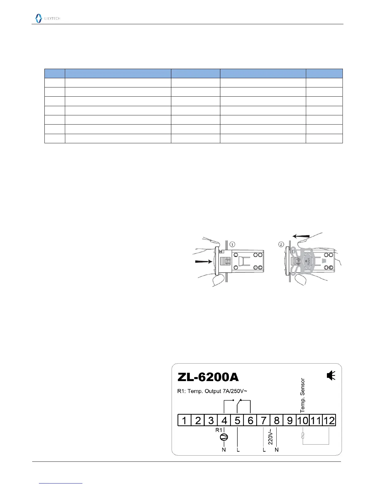
Temp. Output Load Delay Protection
After power supplied, R1 could be energized after F1 time;
After R1 de-energized, it could be energized again after F1.
Installation
1st: Insert into drilling hole; 2nd: Clamp
Attention
Wiring work should be manipulated by certified technicians.
Wrong connection could damage the controller, and the loads. Power supply to terminal 7 and 8 to check the controller. If there is a
multimeter, check the outputs, as well as input, by the help of settings.
Sensor and input signal wires should not be laid together with power supply wire, and even in same pipe.
Sensor wire is better as short as possible. Not wind the redundant length wire to electrical noise equipment.
The loads should be within the specification of the controller output driving ability. If using ac/dc module as load, or tungsten lamp,
or motor, following the below requirements to avoid surging current damaging or shorten the life time of the controller outputs:
For ac/dc module as load, the rated current should be no more 1/10th of output specification under pure resistance.
For tungsten lamp as load, the rated current should be no more 1/15th of output specification under pure resistance.
For motor, the rate current should be no more 1/5th of output specification under pure resistance.
For example: if drive a 1500W tungsten lamp with 7A
(pure resistance spec.) relay, the relay contactor will
be burnt immediately.
Don’t touch inside components;
Avoid installing controller in the following
environment:
More wet than 90%RH, or easily dew; Vibrating, or will
be shocked; Possible sprayed; Under erosive air; Under
explosive air.
Electrical Wiring

 Loading...