8
20
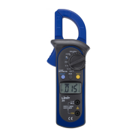
Voltage measurement DC and AC (see fig 1)
1. Insert the red test lead into the VΩ terminal and the black test
lead into the COM terminal.
2. Set the rotary switch to V
... position for DC or V~ for AC.
3. Connect the test leads across with the object being measured.
The measured value shows on the display.
Note
• The instrument has an input impedance of approx.10MΩ. This
loading effect can cause measurement errors in high impedance
circuits. If the circuit impedance is less than or equal to 10kΩ, the
error is negligible (0.1% or less).
Current measurement AC (see fig 2)
Warning
Never attempt an in-circuit current measurement where the vol-
tage between terminals and ground is greater than 600 V.
1. Set the rotary switch to 2/20 A or 200/400 A position.
2. Open the jaws and center one of the conductor. Only one con-
ductor at each time can be measured. The measured value
shows on the display.
Note
• Displays OL selected range is overload, it is required to select a
higher range.
Resistance measurement (see fig 2)
1. Insert the red test lead into the VΩ terminal and the black test
lead into the COM terminal.
2. Set the rotary switch to Ω position. Displays shows Ω.
3. Connect the test leads across with the object being measured.
The measured value shows on the display.
manual_limit20 05-05-26 18.53 Sida 11