Do you have a question about the Lincoln Electric POWERWAVE 655/R and is the answer not in the manual?
Covers California Proposition 65, engine safety, and electric/magnetic field hazards.
Addresses electric shock, fumes, gases, and arc ray hazards during operation.
Details prevention of fires, explosions from sparks, and safe handling of gas cylinders.
Precautions for arc welding, and transformer/rectifier welder safety.
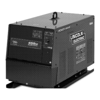
Key performance and operational specifications for the Power Wave 655/R.
Essential safety guidelines for equipment installation, location, grounding, and lifting.
Instructions for connecting input power, fuses, wires, and changing input voltage.
Guidance on multiple power waves, cable connections, and inductance effects.
Procedures for negative polarity, voltage sensing, and board interconnections.
Details on external I/O, gear box, and DIP switch settings for configuration.
Essential safety instructions to follow before operating the welding machine.
Explanation of common symbols appearing on the machine or in the manual.
Overview of the Power Wave, its processes, equipment, limitations, and duty cycle.
Description and location of all operator controls and adjustments on the machine's front panel.
Descriptions of Constant Voltage and Pulse welding modes.
Lists optional, factory installed, and field installed accessories for the Power Wave.
Safety guidelines to follow before performing any maintenance on the equipment.
Procedures for cleaning, inspection, and calibration of the welding machine.
Overview of the Power Wave 655/R as a modular, digitally controlled inverter welding power source.
Explanation of input voltage application and the precharge sequence during startup.
Description of the switch boards and main transformer's role in power conversion.
Details on the function and interaction of various internal PC boards within the system.
Function of the Control Board and description of protective circuits.
Explanation of IGBT operation and Pulse Width Modulation (PWM).
Guidance on using the troubleshooting guide, PC board issues, status LED, and error codes.
Procedures for testing components like capacitors, switch boards, and rectifiers.
Guides for removing and replacing key components like rectifiers, boards, and transducers.
Procedures for calibrating the machine and re-testing after repairs.
Wiring diagrams for different machine codes (10630, 10863, 11410).
Full schematics for machines based on specific codes (10630, 10863, 11410).
Schematics and assembly diagrams for various PC boards including Devicenet, Ethernet, Control, and others.
| Input Voltage | 200-600 V |
|---|---|
| Input Phase | 3-Phase |
| Input Frequency | 50/60 Hz |
| Output Current Range | 5 - 655 A |
| Efficiency | 85% |
| Processes | MIG, Flux-Cored, Stick, TIG |
| Duty Cycle | 100% at 655A |
| Wire Feed Speed | 50-700 IPM |