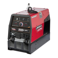
Do you have a question about the Lincoln Electric RANGER 305G EFI and is the answer not in the manual?
| Open Circuit Voltage | 80V |
|---|---|
| Frequency | 60 Hz |
| Max Output | 305A |
| Welding Processes | Stick, TIG, MIG |
| Auxiliary Power | 120/240V |
| Voltage Output | 120/240V |
| Phase | Single |
| Engine Type | Gasoline |
Essential safety guidelines for operating and maintaining welding equipment.
Details on hazards from engine exhaust, EMF, electric shock, arc rays, fumes, fire, and cylinders.
Specific warnings regarding diesel and gasoline engine exhaust emissions.
Safety measures against shock, arc rays, fumes, fire, and cylinder hazards.
Instructions on navigating and utilizing the troubleshooting guide effectively.
Steps for diagnosing and resolving issues related to the machine's PC boards.
Diagnosing and resolving issues related to welding output and auxiliary power.
Identifying and fixing problems related to engine starting, idling, and power output.
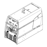
Detailed steps for safely removing and reinstalling the machine's outer covers.
Procedures for testing rotor winding resistance, voltage, and stator winding integrity.
Testing rectifier, chopper module, control boards, potentiometers, receptacles, and solenoids.
Step-by-step guide for removing and replacing the output rectifier bridge and choke.
Procedures for removing and reinstalling the field bridge rectifier.
Instructions for removing and replacing the weld control board and chopper module.
Procedures for removing and replacing the idle solenoid and stator/rotor assemblies.
Procedures and specifications for verifying machine performance after repairs.