Section
Page
- C8
JULY - 2005
Copyright 2005
Printed in U.S.A.
One Lincoln Way
St. Louis, Missouri 63120-1578
(314) 679-4200
FORM 403572
-130G
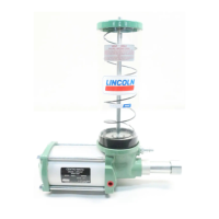
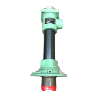
Model No. 83834
AIR OPERATED
GREASE PUMP
Series "D"
*Based on Lubricants that are free from entrapped air. Lubricants that are aerated will reduce output of pump.
The 83834 Pump is used as the Pumping Unit for a Centralized Lubrication System having a Single Line Circuit of SL-1, SL-32, or SL-33
Injectors. Dispenses grease up through NLGI No. 1.
It is an air-operated, single-stroke pump requiring air for both forward and return stroke and discharges
*
2.15 cu. in. of lubricant into the
circuit for each pump stroke (Lubrication Cycle).
The total quantity of lubricant needed for the lubrication cycle of the system must not exceed the amount of lubricant discharged per
pump stroke.
TO PRIME SYSTEM
SUPPLY LINES: After pump reservoir has been filled with recommended lubricant, turn vent plug counter-clockwise one complete turn and
operate pump until lubricant flows freely from opening in vent plug to expel air pockets trapped between the pump and the supply line connection.
Tighten vent plug. Remove all plugs in dead ends of the injector manifolds and supply lines. Operate pump until lubricant flows from any plug
opening. Close opening with plug. Continue operating pump until lubricant flows from another plug opening. Repeat this procedure until all
supply lines are primed and plug openings closed.
FEEDER LINES: Fill each feed line with lubricant before connecting lines to outlet of injectors and bearings. This will prevent having to cycle
each injector for every inch of feed line between injector and bearing.
INJECTORS: Check each injector for proper operation. Injector stem moves when injector discharges lubricant to bearing. This may require
cycling system several times. After checking injectors for operation, adjust injectors for the volume required for each bearing.
TO FILL RESERVOIR
Use a manual filler pump to fill reservoir through
the filler fitting in the pump body. Attach coupler
on delivery hose to filler fitting. Stroke filler pump
handle until lubricant weepage is noted at air vent
hole in the reservoir (lower portion of follower must
rise beyond air vent hole to expel entrapped air from
lubricant).
NOTE: When filling the reservoir, caution should
be used as extreme pressure can cause damage to
RATIO
LUBRICANT
OUTPUT
(CU. IN.)
RESERVOIR
CAPACITY
AIR INLET
LUBRICANT
OUTLET
LUBRICANT OPERAING PRESSURE (PSI)
TYPE OF
SYSTEM
MINIMUM MAXIMUM RECOMMENDED
1,850 3,500 2,500
SL-1 with with with
25:1 *2.15 4 LBS. 1/4 NPT 1/4” NPT 75 PSIG Air 140 PSIG Air 100 PSIG Air
(120 Cu. In.) Female Female SL-32 1,200 3,500 1,500
SL-33 with with with
50 PSIG Air 140 PSIG Air 60 PSIG Air