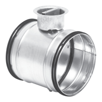
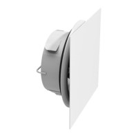
Constant/variable flow dampers
DAVU
Setting of flow limits
The two flow limits are set by moving the end stops. At delivery the stops are set at lar-
gest possible distance. If you want to limit the flow span proceed in the following way:
1. The one flow limit is set by turning the spindle so that the scale arrow points at the
desired flow and thereafter move one of the end stops close up to the clamp's one
heel and lock the stop there.
2. The other flow limit is set by turning the spindle so that the scale arrow points at this
flow and thereafter move the other end stop close up to the clamp's other heel and
lock this stop there.
3. The motor shall then be adapted so that the regulating span 2–10 V adapts to the
thus set flow span. This is done by a push on the "gear disengagement" button. The
motor then automatically performs a stroke between the flow limits.
Choice of flow
The flow is chosen by feeding a control signal. This signal, 2–10 V, sets the motor in a
proportional position between the flow limits.
BELIMO
R
Made in Switzerland
LM24 A-SX
0
1
ews
Technical data for the motor
LM 24 A-SX
Power supply ............................. AC 19,2–28,8 V, 50/60 Hz
DC 21,6–28,8 V
Power consumption .................. 2 W
For wire sizing ........................... 4 VA
Connection ................................ Cable 1 m, 4×0,75 mm²
Operating angle ......................... Max. 95°, adjustable 0–100 %
Torque at nominal voltage ......... Min. 5 Nm
Direction of rotation ................... Switch selectable 0/1
Position at Y=0 V ....................... Switch selectable 0 or 1
Position indication ..................... Mechanical
Running time for 90° ................. 150 s
Sound power level ..................... 35 dB (A)
Protection class ......................... III Safety extra-low voltage
Protection type .......................... IP 54
Ambient temperature range ...... -30 to +50 °C
Ambient humidity ...................... 95 % RH
–
+
1
235
U
YDC 0–10
 Loading...