EasyManua.ls Logo

Linear Technology 789 - User Manual

Linear Technology 789
7 pages
Print Icon
To Next Page IconTo Next Page
Loading...
QUICK START GUIDE FOR DEMONSTRATION CIRCUIT 789
SINGLE CELL LI-ION BATTERY CHARGER WITH COMPARATOR
1
LTC4062
DESCRIPTION
Demonstration circuit 789 is a complete constant-
current, constant-voltage battery charger for one
Lithium-Ion cell and includes a comparator which can
be used to monitor battery voltage or other voltages.
The LTC4062EDD used on this demo circuit features
an internal P-Channel power MOSFET with a unique
thermal feedback loop that reduces the output current
under high ambient temperature and/or high power
dissipation conditions. This feature allows the charger
to provide higher charge currents under normal con-
ditions and still provide safe charging under abnormal
conditions such as high ambient temperature, high
input voltage or low battery voltage.
Jumpers on the board allow charge currents from
50mA to 1A to be programmed and several charge
termination methods to be used. A jumper also se-
lects either the battery voltage or an external voltage
for the comparator input. Terminals are provided for
the comparator input and output, shutting down the
charger, monitoring charge current and programming
the minimum charge current level for termination
(I
DETECT
). Two LEDs are included, one indicates
when the charge current has dropped below the
minimum charge current termination level and the
second indicates the comparator output state.
The IC is available in a 10-Pin 3mm x 3mm DFN
thermally enhanced package featuring an exposed
bottom-side metal pad for soldering to the PC board.
Design files for this circuit board are available. Call
the LTC factory.
LTC is a trademark of Linear Technology Corporation
Table 1. Typical Specifications (25°C)
Input Voltage Range V
IN
4.3 to 8V (upper range limited by PC board power
dissipation)
Input UnderVoltage Lockout 3.8V
Output Float Voltage V
BAT
(constant voltage mode) 4.2V ±0.5%
Output Current I
BAT
(constant current mode) From 50mA to 1A ± 8% (selected by jumpers)
Current Monitor Output 1V ±5% @ Full Current
Charge Termination Timer 3 Hours ±10%
Charge Termination Threshold Current (I
DETECT
) 25mA, 50mA, 100mA ± 10%
Comparator Threshold 2.910V ±3%
Question and Answer IconNeed help?

Do you have a question about the Linear Technology 789 and is the answer not in the manual?

Summary

Circuit Description and Features

Device Operation and Configuration

Charge Termination Methods

Explains charge termination using JP1, including timer and minimum current options.

Charge Current and IDETECT Selection

Details jumper settings (JP2, JP3, JP4) for charge current and termination threshold.

CHRG LED Status Indicator

Describes the function of the CHRG LED indicating charge current status.

Current Monitor Terminal Function

Explains how to monitor charge current and program custom currents.

Comparator Input Configuration

Details the COMP IN terminal for comparator input selection.

Quick Start Procedure Guide

Additional Comments and Features

Shutdown Mode and Jumper Interactions

Covers low quiescent current shutdown and jumper interactions for programming.

Custom Charge Current and Termination Settings

Explains programming custom charge currents and termination levels via resistors.

Termination Method Defeat and Waveform Behavior

Details defeating internal termination and output sawtooth waveform characteristics.

Evaluation Aids and Circuit Notes

Provides tips for evaluating the circuit using timing capacitors and input resistors.

Overview

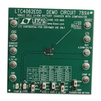
This document describes the LTC4062 Single Cell Li-Ion Battery Charger with Comparator Demonstration Circuit 789 (DC789A).

Function Description:

The DC789A is a complete constant-current, constant-voltage battery charger designed for a single Lithium-Ion cell. It incorporates the LTC4062EDD IC, which features an internal P-Channel power MOSFET and a unique thermal feedback loop. This thermal feedback mechanism automatically reduces the output current under conditions of high ambient temperature or high power dissipation, ensuring safe charging even in abnormal environments such as high input voltage or low battery voltage. The circuit also includes a comparator that can be used to monitor either the battery voltage or an external voltage. Terminals are provided for the comparator input and output, charger shutdown, charge current monitoring, and programming the minimum charge current level for termination (IDETECT). Two LEDs are integrated: one indicates when the charge current has dropped below the minimum charge current termination level (CHRG LED), and the other indicates the comparator output state (COMP LED). The LTC4062EDD IC is supplied in a 10-Pin 3mm x 3mm DFN thermally enhanced package with an exposed bottom-side metal pad for improved thermal performance.

Important Technical Specifications (at 25°C):

  • Input Voltage Range (VIN): 4.3V to 8V (upper range limited by PC board power dissipation).
  • Input Under Voltage Lockout: 3.8V.
  • Output Float Voltage (VBAT, constant voltage mode): 4.2V ±0.5%.
  • Output Current (IBAT, constant current mode): Selectable from 50mA to 1A ± 8% via jumpers.
  • Current Monitor Output: 1V ±5% at full current.
  • Charge Termination Timer: 3 Hours ±10%.
  • Charge Termination Threshold Current (IDETECT): Selectable at 25mA, 50mA, 100mA ± 10%.
  • Comparator Threshold: 2.910V ±3%. The internal comparator reference voltage is 1.00V ± 1.2%, with 50mV of hysteresis.

Usage Features:

The demonstration circuit offers flexible configuration through several jumpers:

  • Charge Termination Methods (JP1):
    • "TIMER" (lower position): Terminates the charge cycle after a set timer period (3 hours, determined by capacitor C2). This is suitable for fully charging a depleted battery at C/2 to 1C current levels.
    • "ITERM" (upper position): Selects minimum charge current termination (IDETECT). The charge cycle ends when the current drops below a programmed threshold after the battery reaches the constant voltage portion.
    • Middle position: Disables on-board termination, allowing for external user-defined termination.
  • Charge Current and Termination Current Selection (JP2, JP3, JP4): These jumpers work in combination to program various charge currents (e.g., 1A, 500mA, 200mA, 100mA) and corresponding IDETECT levels (e.g., 100mA, 50mA, 25mA).
    • ICHG-1 (JP3) and ICHG-2 (JP2): Select different charge currents. ICHG-2 can drop the charge current to 1/5 of the programmed current, useful for USB-powered applications.
    • IDET (JP4): Determines the charge current level for termination and the threshold for the CHRG LED to turn off.
  • Comparator Input Selection (JP5):
    • "BAT" (lower position): The comparator monitors the battery voltage.
    • "EXT" (upper position): The comparator's non-inverting input is connected to the COMP IN terminal, allowing monitoring of an external voltage.
  • CURRENT MONITOR Terminal: This terminal provides a voltage proportional to the charge current (1V indicates 100% of the programmed current). It can also be used to program custom charge currents by removing JP3 and connecting an external programming resistor from this terminal to ground.
  • ENABLE Terminal: Pulling this terminal high puts the charger into a low quiescent current shutdown mode.
  • LED Indicators:
    • CHRG LED: Illuminates when the charge current is greater than the selected IDETECT level, regardless of the termination method. It turns off when the charge current drops below IDETECT.
    • COMP LED: Driven by the open-drain comparator output, indicating the comparator's state.

Quick Start Procedure:

The device can be evaluated using either an actual Li-Ion battery or a battery simulator (adjustable power supply with a load resistor).

  1. Initial Setup: Set the TERMINATION METHOD jumper (JP1) to ITERM (upper), IDET jumper (JP4) to 100mA (lower), ICHG-2 jumper (JP2) to "C" (upper), ICHG-1 jumper (JP3) to HIGH (upper), and COMP jumper (JP5) to BAT (lower). This configures the charger for 1A charge current, 100mA IDETECT termination, and battery voltage monitoring.
  2. Connections: With input and battery simulator power supplies at 0V, connect the input power supply to VIN and GND, and the battery simulator to BAT and GND. An ammeter can be placed between BAT and the simulator's positive terminal to measure charge current. A DVM should be connected to BAT and GND to measure battery voltage.
  3. Charging Simulation:
    • Slowly increase the input supply voltage to 5V. At approximately 3.8V (undervoltage lockout), the CHRG LED will turn on, and preconditioning trickle charge (100mA) will begin. The COMP LED will be off if the battery voltage is below 2.910V.
    • Adjust the battery simulator power supply to 3V. At approximately 2.9V, the charge current will increase to the programmed 1A constant current.
    • Slowly increase the battery simulator voltage to simulate the battery accepting charge. As the simulator approaches 4.200V, the charge current will drop as the charger enters constant voltage mode.
    • When the charge current drops below the 100mA IDET threshold, the charge current will drop to 0, the CHRG LED will turn off, and the charge cycle will end.
    • If timer termination is selected, the CHRG LED will turn off when the current drops below 100mA, but charging continues until the 3-hour timer ends.
  4. Recharge Cycle: After termination, if the battery voltage drops approximately 100mV, a recharge cycle will begin (50% of the programmed time if timer termination is selected).
  5. Comparator Functionality: Reducing the battery simulator voltage to approximately 2.910V will cause the comparator to change states (COMP LED off). The micropower comparator operates from battery power, allowing it to be active even when input power is removed.

Maintenance Features:

  • Speeding up the Timer: For evaluation purposes, the 3-hour timer can be accelerated by replacing the timing capacitor (C2) with a smaller value (e.g., 300pF for approximately 30 seconds).
  • Custom Charge/Termination Currents: Other charge currents and minimum charge current termination levels can be programmed by replacing JP3 with an external resistor from the CURRENT MONITOR terminal to ground, or by selecting a suitable resistor for R5, respectively.
  • Input Capacitor Transient Minimization: A 1 Ohm resistor in series with the ceramic input capacitor helps minimize transient voltages when the input voltage is quickly applied.
  • Sawtooth Waveform (No Battery, ITERM): If minimum charge current termination is used without a battery, a sawtooth waveform of several hundred mV p-p will appear at the charger output. The frequency depends on the output capacitor (e.g., 40Hz with a 2.2µF output capacitor), which may cause the CHRG LED to appear dim or flash briefly.

Linear Technology 789 Specifications

General IconGeneral
BrandLinear Technology
Model789
CategoryMotherboard
LanguageEnglish