EasyManua.ls Logo

Link Controls VEK M2H - User Manual

Link Controls VEK M2H
2 pages
Print Icon
To Next Page IconTo Next Page
Loading...
1b 2a1a
24V 2b0V
1
22.50 74.00
80.00
1 2 3 4
ON DIP
5
6 7 8
24V
1b
2b
2a
0V
1a
1
2
1
2
1
2
5'
sensitivity ch. 1
sensitivity ch. 2
frequency
5' holding time
direction mode
output mode
*) direction mode: pulse on covering both loops
normal mode: pulse only on channel 2 (after covering)
*) flashing = tuning and loop frequency signalization
**) may be changed by setting jumper on the board
operating voltage
24V AC/DC ±10 %
power
detector is tuning
loop free
covered / pulse signal
loop failure
detector status
relays 250mA / 24V AC/DC relay 1
(min. 1mA / 5V) relay 2 **) **)
off
flashing *)
on
on
off
off
off
off
on
on
LED green LED red n.o. n.c.
low . . . . . . . high
low
5 minutes
off
presence
high
on
pulse *)
1
2
Connect Loops to
these terminals
Green Flashing, Red OFF:-
Green ON, Red OFF:-
Red ON, Green ON:-
Green ON-OFF-ON:-
Red ON, Green OFF:-
Red OFF, Green OFF:-
0V
24V
Relay 2
Relay 1
Loop Connections
L.E.D. Functions
Detector is Tuning
Loop Free
Loop is Covered
Pulse Output
Loop Fail
Power OFF
Loop Detector Layout
Operating Instructions
1. Connect the power, ground, loop & output (See Terminal & Loop Connections).
2. Sensitivity of Loop 1 is set by switches `1` & `2` (See Function Settings).
3. Sensitivity of Loop 2 is set by switches `3` & `4` (See Function Settings).
Terminal Connections
Title:- Drawing No:-
Revision No:-
Drawn By:-
Checked By:-
Page No:-
Rev Date:-
Date:-
Appr' By:-
Stuart Rd, Manor Park, Runcorn, Cheshire, WA7 1TS
T: +44 (0)1928 579050
www.linkcontrols.co.uk
F: +44 (0)1928 579259
sales@linkcontrols.co.uk
Link Controls
MFZ
LC-1687
26/11/99
B 25/02/09
1 of 2
S.B.P.
R.A.H. S.L.
VEK M2H LOOP DETECTOR MODULE
(STOCK CODE: 37-4078)
Function
Loop Free
Loop Covered
Loop Fail
Detector is Tuning
Power Off
1
1
2
2
3
3
Loop 1
Loop 2
Relay Function
As standard, both of the relays are Normally Open (N/O). To change Relay 2 to Normally Closed (N/C),
carefully open the detector housing and place the jumper (JP2) to the following position...
:Normally Open :Normally Closed
Note:- For additional information, please see side of loop detector
Function Settings
DIP Switches 1 & 2 :- Loop 1 sensitivity (4 steps)
DIP Switches 3 & 4 :- Loop 2 sensitivity (4 steps)
DIP Switch 5:- Frequency (High / Low)
DIP Switch 6:- Holding time (5 mins - Infinity)
Note:- Loop will recalibrate after 5 minutes constant detection
DIP Switch 7:- Direction detection
Note:- Directional operation is used for Traffic Management ONLY
DIP Switch 8:- Presence / Impulse selection
Note:- If Impulse operation is selected, the 1st loop to be activated will give a Presence signal when the
2nd loop is clear, a Pulse signal will then be given.
8
8
7
7
6
6
5
5
4
4
4
4
ON
ON
ON
ON
3
3
3
3
2
2
2
2
ON
ON
ON
ON
1
1
1
1
:High
:5mins
:Normal Operation
:Presence Operation
:Low
:Infinite
:Directional Operation
:Impulse Operation
MIN.
MIN.
MAX.
MAX.
Question and Answer IconNeed help?

Do you have a question about the Link Controls VEK M2H and is the answer not in the manual?

Link Controls VEK M2H Specifications

General IconGeneral
BrandLink Controls
ModelVEK M2H
CategorySecurity Sensors
LanguageEnglish

Summary

Loop Detector Layout and Functions

Relay Functionality

Describes the operation of relays, including Normally Open (N/O) and Normally Closed (N/C) configurations.

Detector Configuration Settings

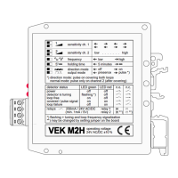
Details the function of DIP switches for sensitivity, frequency, holding time, direction, and presence/impulse selection.

Connections and Indicators

Covers terminal connections, loop wiring, and the meaning of LED status indicators for detector operation.

Operating Instructions

Provides essential steps for connecting power, ground, loops, and outputs for initial operation.

Loop Installation Guidelines

Loop Cable and Size

Specifies requirements for loop cable material, size, and circumference based on the number of turns.

Loop Slot and Sealing

Details recommended depth for loop slots and the importance of using flexible, weather-proof sealant.

Feeder Cable and Placement

Provides guidelines for feeder cable twisting, length, and proper placement away from high tension cables.

Multiple Loop Configurations

Explains how to connect two loops to a single detector for detecting large vehicles, detailing series vs. parallel coupling.