- 10 -
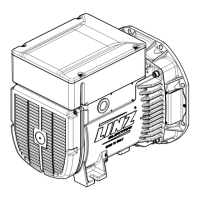
B3/B14 MOUNTING ARRANGEMENT ALTERNATOR TYPE E1C
The B3/B14 mounting arrangement requires the use of a exible coupling between the drive engine and the alternator.
The exible coupling should not cause any axial or radial forces during operation, and will have to be mounted rigidly on
the alternator shaft end. Please follow the instructions below while assembling:
1) Fix one of the two exible coupling halves and the ange to the alternator as shown in Figure 2A. When positioning
the exible coupling half, remember that once coupling is carried out, the rotor must be able to move axially towards
the non-drive end bearing. To make it possible it is necessary that, once the assembling is carried out, the shaft end,
with respect to the ange, is positioned according to Figure 2B.
2) Place the relevant exible coupling half on the revolving part of the diesel engine, as shown in Figure 2C.
3) Insert the coupling’s rubber blocks.
4) Couple the alternator to the drive engine, rstly by screwing, with suitable screws, the ange to the engine (see Fig. 2D).
5) Fix, using appropriate rubber anti-vibration dampers, the engine-alternator unit to the common bed-plate.
Special attention must be paid not to cause any stretching that may aect the natural alignment of the two machines.
6) Make sure that the alternator’s non-drive end bearing has the recommended expansion allowance (min. 2 mm.) and
that it is preloaded by a preload spring.
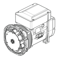
B2 MOUNTING ARRANGEMENT
This type of mounting arrangement too allows direct coupling of alternator to the drive engine. Please follow the instruc-
tions below when assembling:
1) Check that the rotor is positioned correctly, as illustrated in Figure 3A.
2) Remove rotor’s locking components on the non-drive end.
3) Place the alternator next to the drive engine, as illustrated in Figure 3B.
4) Centre and secure the stator to the drive engine’s ange, using the correct M10 screws (tightening torque 40Nm), as
shown in Figure 3C.
5) Centre and secure, the coupling discs to the drive engine’s ywheel working through the air outlet, as indicated in
Figure 3D with the correct M8 screws (tightening torque 25Nm) or M10 screws (tightening torque 40Nm).
Turn the rotor as shown in Figures 4A and B.
After completing the above-mentioned coupling procedures check that the rotor’s axial positioning is correct,
and verify that the expansion allowance between the non-drive end bearing and the axial locking wall is 2 mm,
for SP10 and E1C10, 3 mm for E1C11 and E1C13.
OPERATION
Connecting load cables connections should be carried out by qualied personnel when the machine is
completely stopped (locked out) load cables are unplugged.
Voltage and output frequency:
These alternators are designed to supply only the voltage and frequency specied in the rating plate.
Winding resistences SP10 (Ohms @ 20°C)
Type power (kVA) stator rotor cap.
principal excitation battery charger
50Hz 60Hz 50Hz 60Hz 50Hz 60Hz 50Hz 60Hz 1 polo (uF 450V)
SP10S A 1,7 2 4,21 3,32 17,66 13,58 0,15 0,11 4,61 10
SP10S B 2,2 2,7 2,94 2,5 8,63 7,2 0,1 0,088 3,42 14
SP10S C 2,6 3,2 2,48 1,92 7,36 5,62 0,097 0,85 3,83 16
SP10S D 3 3,7 1,98 1,54 6,13 4,67 0,093 0,081 3,85 16
SP10S E 3,5 4,3 1,55 1,2 4,89 3,75 0,08 0,075 4,1 20
SP10M F 4,2 5 1,2 0,92 3,85 2,84 0,083 0,071 4,85 25
SP10M G 5 6 0,97 0,76 3,21 2,45 0,074 0,062 4,27 25
KVA Winding resistences E1C/2 (Ohm 20 °C) Cap.
Type Stator Rotor (450 V.)
50 Hz 60 Hz Principal* Excitation Battery charger (1 pole) µF
50 Hz 60 Hz 50 Hz 60 Hz 50 Hz 60 Hz
E1C10S B 2.2 2.7 3.04 2.35 9.05 7.1 0.1 0.088 3.4 14
E1C10S D 3 3.7 1.97 1.54 5.9 4.65 0.093 0.081 3.85 16
E1C10S E 3.5 4.3 1.6 1.2 4.8 3.75 0.08 0.075 4,1 20
E1C10S F 4.2 5 1.15 0.92 3.7 2.85 0.083 0.071 4,85 25
E1C10S G 5 6 1 0.76 3.18 2.45 0.074 0.062 3.96 25
E1C10M H 6 7.25 0.66 0.52 1.95 1.53 0.07 0.06 5,62 30
E1C10M I 7 8.5 0.515 0.39 1.57 1.18 0.075 0.062 5.1 40
E1C10M L 8 9.75 0.45 0.35 1.15 0.95 0.073 0.058 6.9 45
E1C11MA 8 9.75 0.42 0.33 1.52 1.13 4.97 45
E1C11MB 10 12.5 0.286 0.22 1.04 0.82 5.83 30+35
E1C11MC 12 15 0.235 0.18 0.8 0.63 6.2 35+35
E1C13M D/2 15 18 0.18 0.135 0.46 0.36 5.87 40+40
E1C13M E/2 18 22 0.155 0.115 0.35 0.29 5.87 30+30+35
* With connections for the higher voltage.
Winding resistences E1C/4 (Ohm 20 °C)
Type power (kVA) stator rotor cap.
principal* 1-4 excitation
50 Hz 60 Hz 50 Hz 60 Hz 50 Hz 60 Hz 1 pole (µF 450V)
E1C13S A/4 5.5 7 0.73 0.52 2.44 1.61 0.83 25+30
E1C13S B/4 7 8.5 0.57 0.39 1.90 1.35 0.94 30+25
E1C13S C/4 8 9.75 0.41 0.28 1.44 0.95 1.04 35+40
E1C13S D/4 9 11 0.35 0.26 1.12 0.74 1.13 40+45
E1C13M E/4 11.5 14 0.23 0.18 0.76 0.54 1.35 35+40+40
E1C13M F/4 12.5 15 0.20 0.16 0.62 0.52 1.41 40+40+40
* With connections for the higher voltage.
Operation in particular settings
If the alternator is going to be used within a soundproof generating set, make sure that only fresh air enters it. This can be
ensured by placing the alternator’s air inlet near the external air intake. You also have to take into account that the amount of
air required by the alternator is:
- SP10: 4 m
3
/min.
- E1C10: 4 m
3
/min.
- E1C11: 5 m
3
/min.
- E1C13: 10 m
3
/min.
 Loading...