- 11 -
VOLTAGE AND REVOLVING SPEED CALIBRATION
Voltage and revolving speed calibration should be carried out by qualied personnel only because of
electrocution hazard.
The alternator’s output voltage measurement should be carried out at the nominal revolving speed.
Small deviations of the outlet voltage can depend on the fact that the revolving speed is dierent from the nominal one.
Keep into account that the output voltage changes proportionally to the squared revolving speed variation, at nominal speed.
If the output voltage needs to be adjusted, (with the alternator locked out) it will be necessary to:
a) increase the capacitor’s excitation capacity to increase voltage;
b) decrease the capacitor’s excitation capacity to decrease voltage.
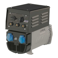
Battery charger circuit
The SP10 and E1C/2 series alternators can be equipped with a battery charger circuit which supplies a maximum
current of 10 A. The rectifier bridge of the battery charger is usually selected for 600 V.-10 A.
Excitation of alternator
As a result of disassembling operations, or because of some unusual failure, the alternator can loose its excitation. In such
a case, after it has been coupled to the drive engine, it is necessary to excite the alternator by applying a 12 Vdc voltage to the
output terminals (only for the time necessary for the excitation and with the alternator set at nominal speed).
It is advisable to connect a 10 A - 250 V fuse in series to one of the two wires going from the batteries to the output terminals.
Rotating rectier assembly inspection
The best way to check the rotating diodes is using a battery and a bulb so that the diode does not need to be disconnected
from its winding.
Using a 12 V battery and a «driving beam» type bulb (about 50 W), you will need to arrange the two connections as shown below,
and the bulb should light up smoothly when connected as illustrated in g. 8 (A: lamp ON, B: lamp OUT).
Bearings
The bearings of the alternators are self lubricated therefore they do not require maintenance for a period of more than 10000
hours. Should you proceed with the overhaul of the genset, it is advisable washing the bearings with a suitable
solvent.
BEARING TYPE
Alternator Drive-end side Opposite drive-end side
SP10 6204-2Z-C3
E1C10 6305-DDU-C3E 6204-2Z-C3
E1C11 6207-2Z-C3 6205-2Z-C3
E1C13 6208-2Z-C3 6305-DDU-C3E
FAULT CAUSE ACTION
Low voltage with
no-load
1)
Too low drive engine RPM
1)
Reset nominal speed for drive engine
2)
Faulty rectifying diode bridge
2)
Replace rectifying diode bridge
3)
Capacitor with low capacitance
3)
Increase capacitor’s capacitance
4)
Winding fault
4)
Check resistance and replace damaged part
High voltage
with no-load
1)
Capacitor with too high capacitance
1)
Reduce capacitor’s capacitance
2)
Too high drive engine RPM
2)
Reset nominal speed for drive engine
Alternator does
not excite
1)
Too low drive engine RPM
1)
Reset nominal speed for drive engine
2)
Connection failure
2)
Check wiring diagram and reset correct connections
3)
Capacitor failure
3)
Replace capacitor
4)
Windings failure
4)
Check winding resistance and replace damaged part
5)
Rectifying diode bridge failure
5)
Replace rectifying diode bridge
Correct voltage
with no-load but
too low voltage
on load
1)
Rectifying diode bridge failure
1)
Replace rectifying diode bridge
2)
Low revolving speed at full load
2)
Adjust governor control to nominal speed
3)
Load is too high
3)
Reduce current supplied
4)
Load PF is too low
4)
Wire a capacitor in parallel with the lowest PF load
Noisy working
1)
Bad coupling
1)
Check and correct coupling
2)
Short circuit in windings or load
2)
Check windings and loads, and change faulty ones
3)
Faulty bearing
3)
Replace faulty bearing
Unstable voltage
1)
Uneven engine rotation
1)
Check drive engine and x
2)
Poor contact within connections
2)
Check and tighten faulty connections
3)
Irregular load
3)
Check loads and remove irregular one
English
 Loading...