4
lci1.com 574-537-8900 CCD-0001763 Rev: 08.07.18
Flow Max
™
12V DC
Fluid Pump by Duraself
Installation and Owner’s Manual
(For Aftermarket Application)
NOTE:
designed with a “taper seal” to create a watertight
connection when hand tightened. Always secure barb
tubing connections with properly-sized stainless steel
clamps to prevent leaks.
NOTE: Never use thread sealing tape or sealing
compounds on threads. Tape or sealing compounds may
enter the pumps and cause a failure.
Rapid cycling may be caused by excessive back pressure
created by one or more of the following within the plumbing
system:
•
•
•
•
feeder lines to faucets.
setting (Fig.3) can be increased by turning the screw
½ turns maximum.
front of pump
pump shutoff
pressure switch
Plumbing The System
1. Install in-line screen (Fig.2A) on the inlet side of the
pump (Fig.1) to prevent debris from entering the pump.
2. Using the supplied ½" swivel connectors (Fig.2B)
of the pump and the inlet port of the in-line screen (Fig.1).
NOTE: The pump ports and strainer should not be
oscillation may be transmitted through rigid plumbing,
causing noise and possibly loosening or cracking
components.
3.
minimum of ½" inner diameter reinforced hose for main
lines.
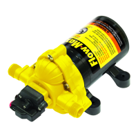
outlet port
inlet port
ground wire
positive lead
A
B
inlet port
Fig.1
Fig.2
Fig.3