5
lci1.com 574-537-8900 CCD-0001763 Rev: 08.07.18
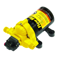
Flow Max
™
12V DC
Fluid Pump by Duraself
Installation and Owner’s Manual
(For Aftermarket Application)
IF THE WIRE IS TOO SMALL, LOW VOLTAGE WILL
AFFECT THE PUMP PERFORMANCE AND CAN CREATE
A FIRE HAZARD.
Electrical Connections
NOTE: The pump should be on a dedicated circuit protected
The chart lists the minimum wire size for a 10% voltage
drop on a 12V DC 10 amp circuit. Length is the distance
in feet from the power source to the pump and back to
ground.
Sanitizing
Potable water systems require maintenance to keep
components working properly to deliver a consistent
storing. After a period of time in storage or any time the
system is opened or contaminated, sanitizing the system
is recommended. Systems with new components or ones
that have been subjected to contamination should also be
disinfected.
1. Determine the amount of common household bleach
needed to sanitize the tank.
A. Multiply the gallons of tank capacity by 0.13. The
result is the number of ounces of bleach needed to
sanitize the tank.
2. Mix the bleach with water in a container.
3.
with potable water.
4. Open all faucets (hot and cold) and allow water to run
faucets.
5. Allow 4 hours contact time to disinfect the tank.
6. At the conclusion of the prescribed contact time, drain
the tank.
7.
system once or twice until the chlorine odor has decreased.
The residual chlorine odor and taste is not harmful.
1. Determine the proper wire size for good pump operation.
2. Install a 15 amp (ignition protected) switch on the
positive lead (red wire) (Fig.1). The switch should be
mounted in an easily accessible location.
NOTE: For marine use, a 15 amp marine duty (ignition
protected) switch is required.
3. Connect the positive lead (red wire) to the switch.
4. A second positive lead wire of the same size should be
connected to the battery from the switch.
NOTE: A 10 amp fuse is required as per applicable codes.
5. Connect the negative ground wire (black) to the negative
(black) terminal of the battery.
NOTE: The ground, positive and switch wires must all be
of the same gauge.
NOTE:
unattended.
Pump Wire Chart
Length AWG
0-25 16
25-50 14
50-70 12
70-110 10