5. GENERAL INFORMATION
5.1. Sales information
When purchasing make sure to check technical condition and equipment of the mower.
Request the Seller to carefully complete the Warranty Card and claim vouchers. Lack of, e.g.
date of purchase or dealer’s stamp will render any possible claims addressed by user
unrecognised.
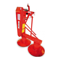
The manufacturer delivers mower Z-178 i Z-178/1 in complete condition but with cutting unit
cover removed.
Cutting unit cover should be installed by user (purchaser) on their own (see Assembling mower).
5.2. Equipment and spare parts
Mower Z-178 comes with the following basic equipment:
• instruction manual with parts catalogue and warranty card 1 pce
• special wrench (welded) 1 pce
• knives (in package) 12 pcs
On purchaser’s special request and on extra charge it is possible to order the following by
contacting seller (manufacturer):
• U-joint shaft,
• rectangular warning light plates,
• warning triangle for slow-moving vehicles.
5.3. Design and working principle
Rotary mower Z-178 is composed of the following main assemblies (Fig. 1):
• linkage frame
• central beam (frame),
• main frame,
• cutting unit,
• drive train,
• drive train and cutting unit covers,
• safety device.



 To Next Page