Page ii
REV. 6-A-060818
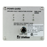
PGR-3100 Ground-Fault Indication System
TABLE OF CONTENTS
1 FEATURES .................................................................... 1
2 DESCRIPTION ............................................................ 1
3 INSTALLATION .......................................................... 1
4 TECHNICAL SPECIFICATIONS
.................................. 4
LIST OF FIGURES
1 PGR-3100 Outline and Mounting Details ......... 1
2 Connection Diagram for an Ungrounded
240- to 600-V System ......................................... 2
3 Connection Diagram for Ungrounded
Systems above 600 V ......................................... 2
4 Connection Diagram for
Resistance-Grounded System up to 600 V ....... 3
5 Connection Diagram for a
Resistance-Grounded System above 600 V .....3
DISCLAIMER
Specifications are subject to change without notice.
Littelfuse, Inc. is not liable for contingent or consequential
damages, or for expenses sustained as a result of a mal-
function, incorrect application, or incorrect adjustment.