Do you have a question about the LNS ECO LOAD Series and is the answer not in the manual?
Do not handle without knowledge; observe safety instructions for bar feed system and lathe.
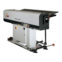
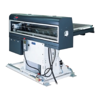
Provides dimensional drawings and layout of the ECO LOAD machine and its relation to the lathe.
Lists technical specifications like bar diameter, length, weight, and power supply.
Illustrates the recommended method for lifting the bar feeder system using a crane.
Specifies the optimal distance between the feeder and lathe for efficient operation.
Details the steps for adjusting the vertical position of the bar feeder.
Explains how to ensure the feeder is level and aligned horizontally with the lathe.
Provides instructions on how to securely fasten the machine to the floor.
Instructions for assembling the loading system components using provided bolts.
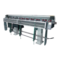
Steps for installing and securing the bar magazine, including ramps and support.
Details the requirements for power supply and compressed air connections for the feeder.
A schematic illustrating the pneumatic components and their connections within the system.
Explains the function of the emergency stop button and safety switches on the feeder.
Diagram showing the physical arrangement of electrical components and a table identifying them.
Illustrates the internal layout of the electrical control cabinet with component labels.
Detailed electrical circuit diagrams for the machine's control, power, and interface systems.
Explains the purpose and schematic representation of various input and output signals.
Lists and describes the I/O signals for the CPU224 and EM223 modules.
Shows the wiring diagram and pin assignments for the European standard interface.
Shows the wiring diagram and pin assignments for the US standard interface.
General advice on bar placement and pusher-bar function for startup.
Instructions for adjusting the machine's diameter setting using the hand-wheel.
Details how to adjust the loading table's slant based on bar stock cross-section.
Steps for adjusting the loading fingers, including rake and height settings.
Instructions for adjusting the bar stops to ensure single bar loading.
Guidance on selecting and replacing the pusher-bar based on bar diameter.
Recommendations for reducing bar remnants by optimizing bar length calculation.
Explains the function keys (F1-F8) and basic operation of the TD 200 control panel.
Step-by-step guide for accessing and using functions F1-F8 on the TD 200 control panel.
Detailed explanation of functions F1 through F8 and their impact on machine operation.
Identifies the buttons and their functions on the remote control unit.
Instructions for operating the feeder in manual mode.
Step-by-step guide for starting and operating the feeder in automatic mode.
Lists common alarms, their text, and potential causes or descriptions.
Explains the purpose and settings of the function switches for programming.
Provides detailed explanations for different switch settings and their operational effects.
General comments on wiring, relays, inputs, and power supply.
Details two working modes: chuck signal only and chuck signal with M-code.
Timing diagrams for interface signals in Program 1, illustrating signal flow.
Timing diagrams for interface signals in Program 2, including M-function.
A flowchart illustrating a sample programming sequence and dip switch settings.
Provides an exploded view and part list for the FRAME assembly.
Provides an exploded view and part list for the STAND assembly.
Provides an exploded view and part list for the COVER assembly.
Provides an exploded view and part list for the FEEDING DEVICE assembly.
Provides an exploded view and part list for the BAR PUSHER assembly.
Provides an exploded view and part list for the AXIAL DISPLACEMENT assembly.