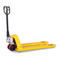
. Draw-bar 2. Pin 3. Axle with hole 4. Elastic pin 5. Fork frame
(Fig. 1)
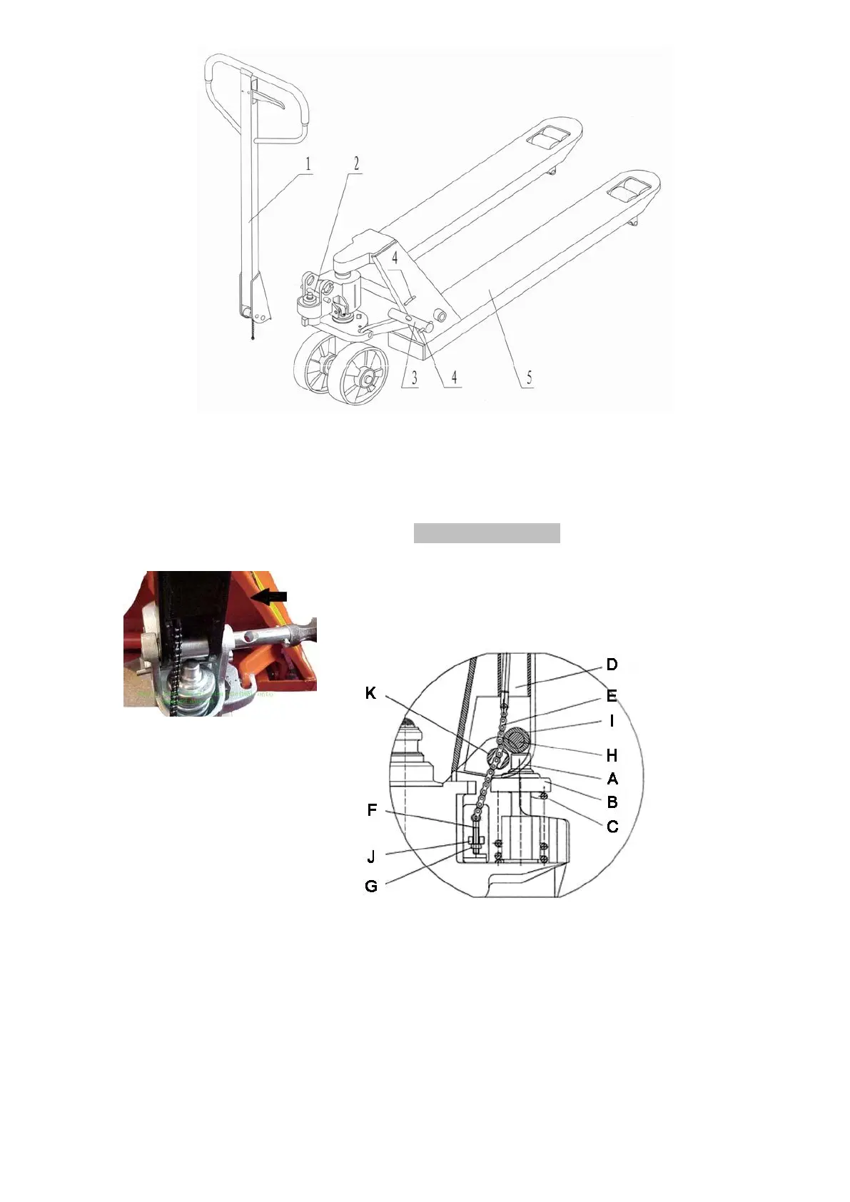
When attaching the handle, you had better squat just behind the pallet truck. Then you:
2.1. Insert the draw-bar onto the pump piston (A), then use a hammer to insert the axle with
hole
(K) into the hydraulic pump and draw-bar from the right to left. (See fig. 2 ).
2.2. Let control handle to the ‘LOWER’ position, then pass
the adjusting nut (G), adjusting bolt (F) and chain (E)
through the hole of axle(K) with your hand (See fig. 3)
2.3. Press the draw-bar (D) down, take away the pin(#2) (See Fig. 1).
2.4. Let the control handle on ‘RAISE’ position, then raise the lever plate (J) with the pin ( #2)
and insert the adjusting bolt(F) into the front slot of lever plate, note to keep the adjusting
nut (G) on the under side of the lever plate(J).
2.5 Use a hammer to tap another elastic pin into the axle with hole (K). The Draw-bar is now
assembled to the pump.