EasyManua.ls Logo

Lochinvar Knight XL 399 - 800 User Manual

Lochinvar Knight XL 399 - 800
44 pages
To Next Page IconTo Next Page
Page #1 background imageLoading...
Page #1 background image
Service Manual
Models: 399 - 800
This manual must only be
used by a qualified heating
installer / service technician.
Read all instructions,
including this manual and the
Knight XL Installation and
Operation Manual, before
installing. Perform steps in
the order given. Failure to
comply could result in severe
personal injury, death, or
substantial property damage.
WARNING
Save this manual for future reference.
KBX-SER Rev E
Question and Answer IconNeed help?

Do you have a question about the Lochinvar Knight XL 399 - 800 and is the answer not in the manual?

Lochinvar Knight XL 399 - 800 Specifications

General IconGeneral
TypeCondensing Boiler
AFUE95%
Fuel TypeNatural Gas or Propane
Water Connection Size2" NPT
EfficiencyUp to 95%
Vent Connection Size4"
Vent TypeDirect Vent or Power Vent
Vent Diameter4"

Summary

Knight XL Commercial Boiler Service Manual

Model Identification

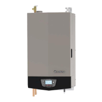
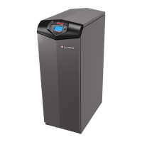
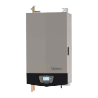
Specifies the available models for the Knight XL Commercial Boiler.

General Warning Notice

Provides a critical warning for installers and users regarding potential hazards.

Hazard Definition Explanations

Safety Alert Symbol Definitions

Defines the meaning of DANGER, WARNING, CAUTION, and NOTICE safety alert symbols.

Pre-Service and Handling Precautions

Installer and User Responsibilities

Outlines essential instructions for installers and users before operation.

Ceramic Fiber Material Safety

Provides safety guidelines for handling ceramic fiber insulation.

Operational Safety and Fluid Guidelines

Boiler Servicing and Operation Precautions

Details safety measures for boiler servicing and operational guidelines.

Boiler Water and Freeze Protection

Covers boiler water quality and recommended freeze protection fluids.

Manual Content Breakdown

Service Section Overview

Lists the topics covered within the Service chapter.

Maintenance Section Overview

Lists the topics covered within the Maintenance chapter.

Troubleshooting Section Overview

Lists the topics covered within the Troubleshooting chapter.

Chapter 1: Service Procedures

Near Boiler Piping Configuration

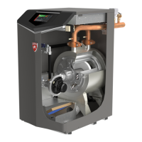
Illustrates typical system components for boiler piping connections.

Knight XL Display Operation

Control Module Inputs

Control Module Outputs

General Operation and Control Modes

Sequence of Operation: Space Heating and DHW

Sequence of Operation: Space Heating and DHW (Cont.)

Display Panel Menu Access

Display Panel Parameter Access

Parameter Reference Tables

General, Temp, Data Logging Parameters

Lists parameters for General, Temperature, and Data Logging sections with access levels.

Parameter Reference Tables (Cont.)

Function, DHW, Outdoor Air, Control, Notification Parameters

Lists parameters for Functions, DHW, Outdoor Air, Control Modes, and Service Notification.

Control Parameter Details

General and Temperature Settings Parameters (A & B)

Details parameters for Boiler Model, User Code, Date/Time, Software, Temperature Units, Setback, and SH settings.

Control Parameter Details (Cont.)

Data Logging, Functions, DHW, Outdoor Air Parameters (C, D, E, F)

Details parameters for Data Logging, Functions, DHW settings, and Outdoor Air Reset.

Control Parameter Details (Cont.)

Outdoor Air Reset Parameters (F)

Details parameters for Outdoor Air Reset, including temperature settings and shutdown.

Control Parameter Details (Cont.)

Boost and Anti-Cycling Parameters (F & G)

Details parameters for Boost Temperature, Boost Time, Anti-cycling Time, and Inlet Temperature Differential.

Control Parameter Details (Cont.)

Control Modes Parameters (H)

Details parameters for SH controlling sensor, SH source, Cascade Address, and Max. Cascade Set Point.

Control Parameter Details (Cont.)

Circulation Pumps and Service Notification Parameters (I & J)

Details parameters for pump delays and service notification settings.

Chapter 2: Maintenance Section

Maintenance and Annual Startup Schedule

Outlines the service and maintenance schedules for technicians and owners.

Chapter 2: Maintenance Procedures

Addressing Reported Problems

Procedure for identifying and correcting issues reported by the owner.

Boiler Area and Interior Inspection

Instructions for inspecting the boiler area and its interior components.

Condensate Trap and Piping Maintenance

Details on cleaning the condensate trap and checking piping for leaks.

Chapter 2: Maintenance Procedures

Flue Vent System and Air Piping Checks

Instructions for inspecting the flue vent system and air piping for blockages or damage.

Water System and Expansion Tank Checks

Covers checks for the water system, pressure, air vents, and expansion tank.

Boiler Relief Valve Inspection

Procedure for inspecting and testing the boiler relief valve.

Chapter 2: Maintenance Procedures

Ignition and Flame Sense Electrode Maintenance

Details on inspecting, cleaning, and replacing ignition and flame sense electrodes.

Wiring and Control Setting Checks

Covers checking ignition ground wiring, boiler wiring, and control settings.

Start-up, Checks, and Burner Flame Inspection

Procedures for performing start-up checks and inspecting the burner flame.

Chapter 2: Maintenance Procedures

Flame Signal Check and Troubleshooting

Guidance on checking the flame signal and troubleshooting low flame signals.

Owner Review and Seasonal Procedures

Covers reviewing the manual with the owner and seasonal shutdown/startup procedures.

Chapter 3: Troubleshooting Section

Pre-Troubleshooting Checks

Lists necessary tools and initial checks before starting troubleshooting.

Control Module Fuse Inspection

Procedure for checking and replacing control module fuses.

Troubleshooting Chart: No Display Issues

Temperature Sensor Resistance Checks

Troubleshooting Chart: Noisy System Issues

Troubleshooting Chart: Fault Messages (Part 1)

Troubleshooting Chart: Fault Messages (Part 2)

Troubleshooting Chart: Fault Messages (Part 3)

Troubleshooting Chart: Fault Messages (Part 4)

Troubleshooting Chart: Fault Messages (Part 5)

Troubleshooting Chart: Fault Messages (Part 6)

Troubleshooting Chart: Fault Messages (Part 7)

Troubleshooting Chart: Fault Messages (Part 8)

Combustion Analysis Procedure

Flue Gas Products Specifications

Lists CO2 and O2 specifications for Natural Gas and Propane flue products.

Combustion Level Troubleshooting

Identifies causes and corrective actions for improper combustion levels.

Gas Valve Adjustment Procedure

Model 399 Gas Valve Adjustment

Procedure for adjusting the gas valve throttle screw on Model 399.

Model 500 and 600-800 Gas Valve Adjustment

Procedure for adjusting the gas valve throttle screw on Models 500 and 600-800.

Chapter 4: Notes Section

Related product manuals