19
7000INST Copyright Lockmasters, Inc. 5/25/11
OPTIONAL
Step 19 – Solenoid Activation ACCESS CONTROL
Step 19A – Access Control Integration
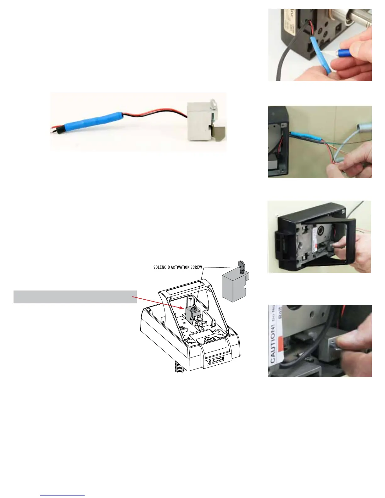
The LKM7000 is shipped with an internal solenoid requiring 24v dc to retract the solenoid
pin. OPTIONAL - In order to use a 12v dc access control unit you’ll need to peel back
the blue heat shrink material away and cut the RESISTOR out of the circuit. (See Photo
right)
Step 19B – When an Access Control system is being used in conjunction with the
LKM7000 it will be necessary to release the Access Control Solenoid Plugger. This
is done by removing the thumb screw located on the top of the Access Control Block.
(See Figure 7 for the location of the Access Control Block.)
NOTE: The solenoid activation screw SHOULD NOT be removed until the Access
Control Unit has been completely installed. If the screw is removed without the
Access Control System online and the door closes an immediate lock-out will
occur.
NOTE: This solenoid is NOT designed for continuous duty.
Solenoid Specications
12 or 24v dc minimum amperage 199 miliamps
LKM7000 Installation
19b - Locate the Solenoid Activation Screw
located in the IBP and remove to release the
Access Control Solenoid Plugger.
(Figure 7) - SOLENOID ACTIVATION SCREW
19b - Close Up
19a - Make the wire connections for the access
control.
RESISTOR
OPTIONAL - Removing the RESISTOR to use
12v dc access control
 Loading...