20
7000INST Copyright Lockmasters, Inc. 5/25/11
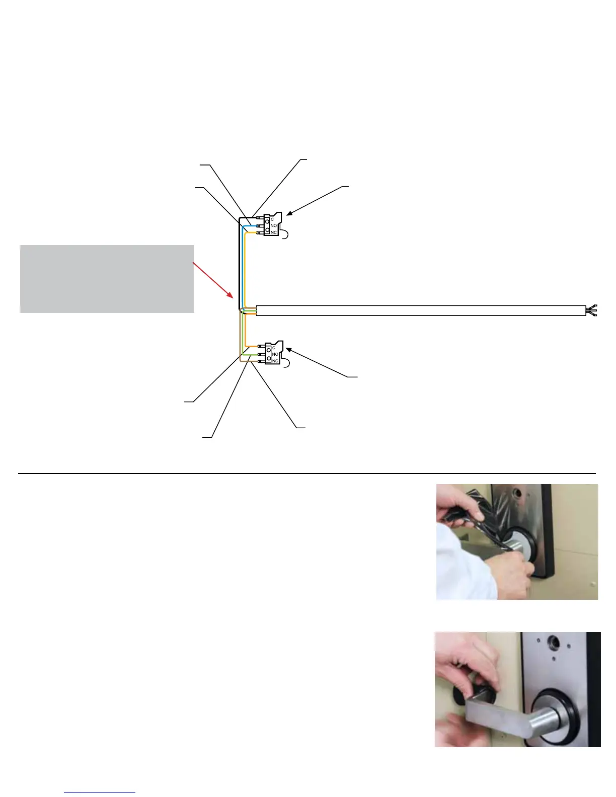
Step 19C – Combination Lock Sensor & LKM7000 Deadbolt
Sensor/REX
The combination lock bolt sensor monitors the extension and retraction of the
combination lock bolt. The LKM7000 Deadbolt Sensor/REX can be used to monitor
the LKM7000 Deadbolt . This can also be used as a Request to Exit switch to shunt
an alarm system. (See Figure 9 - Wire Diagram)
Step 20 – Remove all of the white protective lm from the Front
Plate.
Step 21 – Install the lever handle grip. Lubricate the lever handle
with liquid soap and with the widest end rst slide the foam grip
onto the handle.
LKM7000 Installation
20 - Remove all white protective lm from front
plate (2 pieces).
Blue Wire
Normally Open
Yellow Wire
Normally Closed
White Wire
Common
Deadbolt
Sensor Switch
Orange Wire
Common
Green Wire
Brown Wire
Normally Closed
Combination
Lock Bolt
Sensor Switch
REQUEST TO EXIT (REX)
(Figure 9) WIRE DIAGRAM
The bolt position switch can be used as
an option in order to monitor the posi-
tion of the combination lock bolt and the
lock bolt of the LKM7000.
21 - Remove all white protective lm from
front plate (2 pieces).
 Loading...