EasyManua.ls Logo

Locknetics MG1200 Series User Manual

Locknetics MG1200 Series
8 pages
To Next Page IconTo Next Page
Page #1 background imageLoading...
Page #1 background image
WARNING
Warnings indicate potentially hazardous
conditions, which if not avoided or corrected,
may cause death or serious injury.
CAUTION
Cautions indicate potentially hazardous
conditions, which if not avoided or corrected,
may cause minor or moderate injury. Cautions
may also warn against unsafe practices.
NOTICE
Notices indicate a condition that may cause
equipment or property damage only.
CAUTION
Electromagnetic Lock User’s Guide
MG600/MG1200 Series
The Electromagnetic Lock (Maglock) Series is a surface mounted magnetic lock assembly. It is a narrow profile model available in single
lock format with various sizes (force) designed for standard installation on most types of doors.
Description
Specifications
Precautions
DESCRIPTION MG1200 MG600
Holding Force (lbs) 1200 600
Lock Single Single
Input Voltage (VDC) 12 to 24 12 to 24
Current Draw: @ 12 VDC (amps)
@ 24 VDC (amps)
0.505
0.260
0.505
0.260
Relay Rating:
(resistive)
@ 120 VAC (amps)
@ 30 VDC (watts)
@ 60 VDC (amps)
N/A
3W
N/A
N/A
3W
N/A
Dimensions: inches
(mm)
10.54 x 2.87 x 1.59
(268 x 73 x 40.5)
9.84 x 1.86 x 1.02
(250 x 47.2 x 26)
Weight: lbs
(kg)
10.5
4.8
10.0
4.5
Material: Lock Housing
Armature / Strike Plate
Aluminum
Zinc Plated Steel
Aluminum
Zinc Plated Steel
MG1200DT MG600DT
1200 600
Single Single
12 to 24 12 to 24
0.505
0.260
0.505
0.260
N/A
3W
N/A
N/A
3W
N/A
10.5
4.8
10.0
4.5
Aluminum
Zinc Plated Steel
Aluminum
Zinc Plated Steel
Additional Features: N/A N/A Door Status and Timer Door Status and Timer
Shut off all power before attempting any wiring procedures.
Maintain a clean & safe environment when working in public areas.
● Constantly be aware of pedestrian traffic around the door area.
● Always stop pedestrian traffic through the doorway when performing tests that may result in unexpected reactions by the door.
Always check placement of all wiring before powering up to insure moving door parts will not catch any wires and cause
damage to equipment.
Ensure compliance with all applicable safety standards and building codes upon completion of installation.
MG600 series MG1200 series
10.54 x 2.87 x 1.59
(268 x 73 x 40.5)
9.84 x 1.86 x 1.02
(250 x 47.2 x 26)
Question and Answer IconNeed help?

Do you have a question about the Locknetics MG1200 Series and is the answer not in the manual?

Locknetics MG1200 Series Specifications

General IconGeneral
BrandLocknetics
ModelMG1200 Series
CategoryLocks
LanguageEnglish

Summary

Product Description

Specifications Overview

Safety Precautions and Warnings

Warning

Indicates potentially hazardous conditions, which if not avoided or corrected, may cause death or serious injury.

Caution

Indicates potentially hazardous conditions, which if not avoided or corrected, may cause minor or moderate injury. Cautions may also warn against unsafe practices.

Notice

Indicates a condition that may cause equipment or property damage only.

Important Notices and Installation Tips

Product Power and Wiring Requirements

Details UL listed power supply requirements, common relay output, installation location, and wiring compliance with ANSI/NFPA70.

Printed Circuit Board Schematic

Illustrates correct and incorrect wiring configurations for de-energizing the magnet, addressing residual magnetism.

Installation Tips

Provides guidance on handling the lock face and cleaning surface plating without causing damage.

Electrical Installation

Maglock PCB and Door Sensor Connection

Explains jumper positioning, LED indicators, auxiliary relay output for door position switch, and sensor wiring.

Door Sensor (Reed SW.) Specifications

Details reed switch dry contact ratings and safe operation limits for the door status sensor.

Typical Installation Diagram

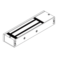
Illustrates common mounting configurations for the maglock assembly on door frames.

Mechanical Installation Procedures

Frame Header Inspection and Hole Drilling

Guides on inspecting the frame header and drilling pilot holes for mounting the lock assembly.

Mounting Plate Attachment

Details disassembling the mounting plate and securing it to the doorframe, advising on screw tension.

Armature Plate Mounting

Explains installing spring pins into the armature and securing it to the door with a hex head screw and washers.

Final Assembly and Wiring Routing

Covers fastening the mounting plate, reassembling the maglock, and routing wiring through the mounting plate.