1 2 3
4 5
8
1 1
6
7
1 0
1
1 2
2 1
1
1
1
1
1
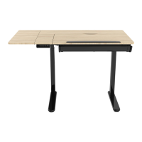
Install the lifting
column
Tabletop sets
Extension sets
Supporting pads
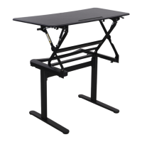
Install the feet
Connect the feet(4) to the lifting column (2), then tighten
the screws(C) with allen key (E).
A
x4
C D E FB
x8 x4 x1 x1
x3
M6x12
M6x16 ST4.2*12 4x4 5x5
ST4.2*19-C
B
x4
E
4x4
C
x8
E
4x4
3
1
9
4
Extension cord
4
1
2
3
4
5
6
7
10
9
8
11
2
Insert
1
Connect the lifting column(3) to the
tabletop sets (1), then tighten the
screws(B) with allen key (D).
Tight the eight screws(B) with 4*4 allen key.
Rotate the lifting column after inserting
it to the end to avoid height difference.
The long side of the lifting column is
parallel to the short side of the table.
8
C
Insert the joint
Tie the cables with cable management
9
5kg
3
Connect all the cables to the adaptor
ET120
50KG
25mm/s
100-240V
730mm
1230mm
950mm(length)
600mm(width)
0~40°
2
0~40°C
600mm(length) 250mm(width) (max 5kg)
Extension size
Tilt range
Hand switch
Power cable
Adaptor holder
Switch cord
Insert the hexagon head of the
lifting column along the guide
slot.
Rotate the lifting column after
inserting, so that the slot is
locked into the screw.
10 Switch cord
7 Power cable
11 Extension cord
Duty Cycle