Do you have a question about the Loctek MT101-SD and is the answer not in the manual?
Key specifications including desktop load-bearing capacity and height adjustment range.
Detailed list of all included parts and their quantities for assembly.
Instructions for connecting desk legs to the desktop and tightening knobs.
Guide on attaching components to corresponding holes using an Allen key.
Instructions for installing plastic caps onto the assembled structure.
Procedure for adjusting the workstation height using side handle grips.
Guidance on placing devices and managing cables for functionality.
Important reminders regarding equipment placement, cable length, and adjustment safety.
Critical warning about avoiding hands near the strut during height adjustment.
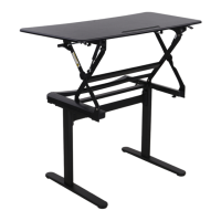
This document provides installation and usage instructions for the Loctek MT101-SD ergonomic workstation. It is designed to be an adjustable desk that can accommodate various working postures.
The Loctek MT101-SD is an adjustable standing desk that allows users to easily transition between sitting and standing positions. The workstation consists of a desktop, two desk legs (left and right), a combined beam, and a mechanism for height adjustment. The height adjustment is controlled by pressing handle grips on both sides of the desktop simultaneously. The desk is designed to support various devices and equipment on its surface, promoting a healthier and more dynamic work environment. Cable management features are integrated to keep the workspace tidy.
Installation: The installation process is divided into three main steps:
Height Adjustment: To adjust the workstation's height, press the handle grips on both sides of the desktop simultaneously. This mechanism allows for smooth and easy transitions between sitting and standing positions. Users are advised to adjust the workstation to a proper height that suits their ergonomic needs.
Device Placement: Place devices and equipment onto the top of the workstation. It is crucial to ensure that all installed equipment is fully on the table and not sticking out over the edge, as this could lead to harm or damage.
Cable Management: The workstation includes cable management features, such as adhesive buckles and a cable management component. These are used to guide and bundle cables, helping to maintain a tidy and organized workspace. The surface also has an area with glue to help fix cables to the table.
Safety Warnings:
This Loctek MT101-SD workstation is designed to be a durable and user-friendly solution for creating an ergonomic and adaptable workspace. Adhering to the installation and usage guidelines will ensure safe and effective operation.
| Brand | Loctek |
|---|---|
| Model | MT101-SD |
| Category | Indoor Furnishing |
| Language | English |