Do you have a question about the Lodar 92 Series and is the answer not in the manual?
Explains the function of Master, 5V, SET, Fault, and Function LEDs for operational status.
Details the connection points on the PCB, highlighting the MOSFET for connections.
Details wiring for power (Plug 1) and output functions (Plugs 2-8).
Details wiring for STOP input (Plug 9) and LIMIT inputs (Plug 2).
Explains jumper settings for Master output mode and jumper necessity for operation.
Covers checking locknut, gland, screws, wire security, and fuse/battery before reconnecting power.
Explains LED blinking, ON, and FLASHES states for operational status.
Transmitter automatically transmits a STOP signal after 30 minutes of inactivity.
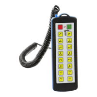
Details transmitter part number, reset button, battery, and working range.
Step-by-step process to re-establish communication between transmitter and receiver.