Logic Digital Controller
User Guide version 3 Page 21 of 31
• Knob B: Slope, 6 to 12dB / octave in 1dB steps
• Knob C: Gain, +/-15dB in 0.2dB steps
The frequency is specified as point where the filter deviates by 3dB from the gain value.
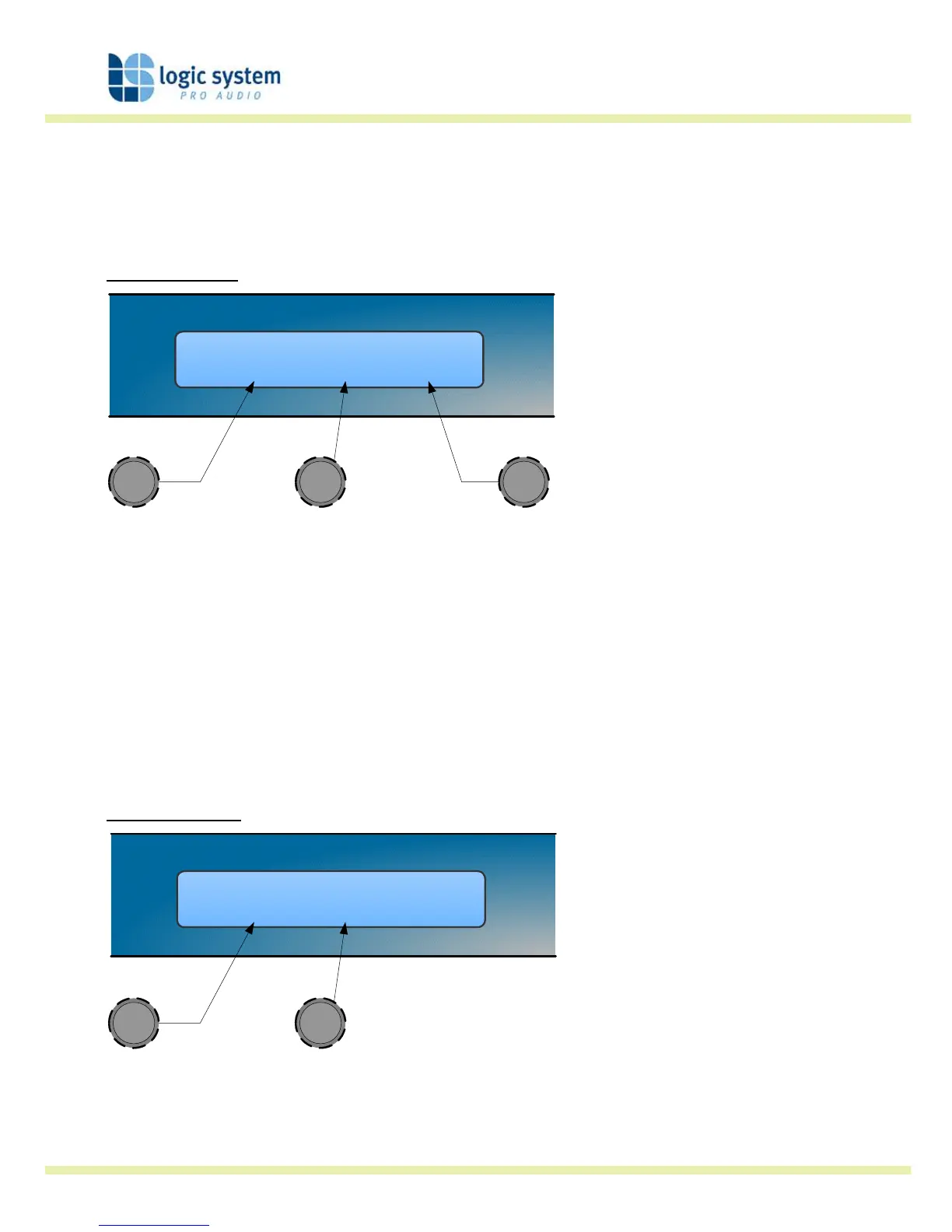
Parametric filters
In A Freq Width Gain
EQ1 100Hz 1.4Q 0.0dB
a
b
c
a b c
• Knob A, Centre Frequency, 10.0Hz to 25.6kHz in variable steps
• Knob B, Width, display selectable, Q or BW (Bandwidth)
BW adjustable from 0.05 to 5 octaves in variable steps
Q adjustable from 14.2 to 0.2 in variable steps
• Knob C, Gain, +/-15dB in 0.2dB steps
Output Channels
Gain and Polarity
Out1 Gain Pol
0.0dB Rev
ab
c
a b
• Knob A: Gain, adjustable in 0.2dB steps from –80 dB to +20dB
• Knob B: Polarity, selectable, normal or reversed with reference to other outputs