Do you have a question about the LogiFind PIC-EK and is the answer not in the manual?
A message of thanks and introduction to LogiFind Tech.
Diagram showing hardware connections for Lab 1 Speaker.
Understand IO operation and interface/drive a buzzer/speaker.
Result of activating the speaker via transistor saturation.
Diagram showing hardware connections for Lab 2 Speaker.
Understand IO operation and interface/drive a buzzer/speaker.
Principle and results for activating speaker via transistor control.
Diagram showing hardware connections for Lab 3 LED control.
Understand IO operation and interface/drive an LED.
Result of setting RD0=1 to turn the LED ON.
Diagram showing hardware connections for Lab 4 LED flashing.
Understand IO operation and interface/drive an LED.
Result of toggling RD0 to make the LED flash.
Diagram showing hardware connections for Lab 5 eight LEDs.
Understand IO operation and interface/drive LEDs.
Result of sending values to RD port for flowing water mode.
Diagram for Lab 6 single digit segment display.
Understand IO operation and interface/drive a SEGLED.
Result of setting segments 'b' and 'c' ON for display.
Diagram for Lab 7 single digit segment display.
Understand IO operation and interface/drive a SEGLED.
Result of sending values 0-9 to RD port for display.
Diagram for Lab 8 four digit segment display.
Understand IO operation and interface/drive a SEGLED.
Result of setting Y0=0 and sending '0' to RD for fourth digit display.
Diagram for Lab 9 four digit segment display.
Understand IO operation and interface/drive a SEGLED.
Result of setting Y1=0 and sending '1' to RD for third digit display.
Diagram for Lab 10 four digit segment display.
Understand IO operation and interface/drive a SEGLED.
Result of setting Y2=0 and sending '2' to RD for second digit display.
Diagram for Lab 11 four digit segment display.
Understand IO operation and interface/drive a SEGLED.
Result of setting Y3=0 and sending '3' to RD for first digit display.
Diagram for Lab 12 four digit segment display.
Understand IO operation and interface/drive a SEGLED.
Result of cycling Y0-Y3 to display '0123'.
Diagram for Lab 13 four digit segment display.
Understand IO operation and interface/drive a SEGLED.
Result of cycling Y0-Y3 and sending values to RD port.
Diagram for Lab 14 joystick, buttons, and segment display.
Understand IO operation and interface/drive a SEGLED.
Result of displaying values on segment display via joystick/buttons.
Diagram for Lab 15 joystick, buttons, and speaker.
Understand IO operation and interface/drive a buzzer/speaker.
Result of activating speaker via joystick or buttons.
Diagram for Lab 16 4x4 keypad and segment display.
Understand IO operation and keypad scan tech.
Result of displaying keypad values on segment display.
Diagram for Lab 17 4x4 keypad and speaker.
Understand IO operation and keypad scan tech.
Result of activating speaker via keypad input.
Diagram for Lab 18 stepper motor control.
Understand how to control a stepper motor.
Result of rotating stepper motor via 4-phase control.
Diagram for Lab 19 LCD1602 character display.
Understand the operation of a Char LCD.
Result of displaying characters on LCD1602.
Diagram for Lab 20 LCD1602 numeric display.
Understand the operation of a Char LCD.
Result of displaying Arabic numerals on LCD1602.
Diagram for Lab 21 LCD1602 number increment.
Understand the operation of a Char LCD.
Result of displaying incrementing numbers on LCD1602.
Diagram for Lab 22 Timer0 and LED control.
Understand the operation of timer.
Result of Timer0 toggling LEDs ON/OFF at intervals.
Diagram for Lab 23 Timer0 and segment display.
Understand the operation of timer.
Result of Timer0 counting displayed on segment display.
Diagram for Lab 24 Timer0 and LCD1602.
Understand the operation of timer.
Result of Timer0 counting displayed on LCD1602.
Diagram for Lab 25 Timer1 and LED control.
Understand the operation of timer.
Result of Timer1 toggling LEDs ON/OFF at intervals.
Diagram for Lab 26 Timer1 and segment display.
Understand the operation of timer.
Result of Timer1 counting displayed on segment display.
Diagram for Lab 27 Timer1 and LCD1602.
Understand the operation of timer.
Result of Timer1 counting displayed on LCD1602.
Diagram for Lab 28 Timer2 and LED control.
Understand the operation of timer.
Result of Timer2 toggling LEDs ON/OFF at intervals.
Diagram for Lab 29 Timer2 and segment display.
Understand the operation of timer.
Result of Timer2 counting displayed on segment display.
Diagram for Lab 30 Timer2 and LCD1602.
Understand the operation of timer.
Result of Timer2 counting displayed on LCD1602.
Diagram for Lab 31 RB0 interrupt with buttons and LEDs.
Understand the operation of RB0 Interrupt.
Result of LEDs returning to initial state upon BUTTON1 press.
Diagram for Lab 32 RB0 interrupt with button and segment display.
Understand the operation of RB0 Interrupt.
Result of segment display resetting upon BUTTON1 press.
Diagram for Lab 33 RB0 interrupt with button and 4-digit display.
Understand the operation of RB0 Interrupt.
Result of 4-digit display resetting upon BUTTON1 press.
Diagram for Lab 34 RB0 interrupt with button and LCD1602.
Understand the operation of RB0 Interrupt.
Result of LCD1602 resetting upon BUTTON1 press.
Diagram for Lab 35 PS2 keyboard and LCD1602.
Understand PS/2 Keyboard operation via microcontroller.
Result of displaying key values on LCD1602.
Diagram for Lab 36 Watchdog timer and LCD1602.
Understand the operation of Watch Dog.
Result of Watchdog timer functionality observed on LCD1602.
Diagram for Lab 37 internal EEPROM and LCD1602.
Understand the operation of internal eeprom.
Result of reading/writing data to EEPROM and displaying on LCD1602.
Diagram for Lab 38 PWM CCP1 and LED brightness.
Understand the operation of PWM.
Result of controlling LED brightness using PWM duty cycle.
Diagram for Lab 39 PWM CCP2 and LED brightness.
Understand the operation of PWM.
Result of controlling LED brightness using PWM duty cycle.
Diagram for Lab 40 CCP2, remote, and LCD1602.
Understand CCP and infrared Remote control.
Result of receiving remote codes and displaying on LCD1602.
Diagram for Lab 41 remote control and speaker.
Understand infrared Remote control operation.
Result of activating speaker by pressing remote keys.
Diagram for Lab 42 RB0 interrupt, remote, and LCD1602.
Understand RB0 interrupt and infrared Remote control.
Result of remote codes triggering interrupt and displaying on LCD1602.
Diagram for Lab 43 8-bit ADC AN0 and LCD1602.
Understand the operation of 8-bit ADC.
Result of displaying 8-bit AN0 ADC sample on LCD1602.
Diagram for Lab 44 8-bit ADC AN1 and LCD1602.
Understand the operation of 8-bit ADC.
Result of displaying 8-bit AN1 ADC sample on LCD1602.
Diagram for Lab 45 8-bit ADC AN2 and LCD1602.
Understand the operation of 8-bit ADC.
Result of displaying 8-bit AN2 ADC sample on LCD1602.
Diagram for Lab 46 8-bit ADC AN3 and LCD1602.
Understand the operation of 8-bit ADC.
Result of displaying 8-bit AN3 ADC sample on LCD1602.
Diagram for Lab 47 8-bit ADC AN4 and LCD1602.
Understand the operation of 8-bit ADC.
Result of displaying 8-bit AN4 ADC sample on LCD1602.
Diagram for Lab 48 8-bit ADC AN5 and LCD1602.
Understand the operation of 8-bit ADC.
Result of displaying 8-bit AN5 ADC sample on LCD1602.
Diagram for Lab 49 8-bit ADC AN6 and LCD1602.
Understand the operation of 8-bit ADC.
Result of displaying 8-bit AN6 ADC sample on LCD1602.
Diagram for Lab 50 8-bit ADC AN7 and LCD1602.
Understand the operation of 8-bit ADC.
Result of displaying 8-bit AN7 ADC sample on LCD1602.
Diagram for Lab 51 10-bit ADC AN0 and LCD1602.
Understand the operation of 10-bit ADC.
Result of displaying 10-bit AN0 ADC sample on LCD1602.
Diagram for Lab 52 10-bit ADC AN1 and LCD1602.
Understand the operation of 10-bit ADC.
Result of displaying 10-bit AN1 ADC sample on LCD1602.
Diagram for Lab 53 10-bit ADC AN2 and LCD1602.
Understand the operation of 10-bit ADC.
Result of displaying 10-bit AN2 ADC sample on LCD1602.
Diagram for Lab 54 10-bit ADC AN3 and LCD1602.
Understand the operation of 10-bit ADC.
Result of displaying 10-bit AN3 ADC sample on LCD1602.
Diagram for Lab 55 10-bit ADC AN4 and LCD1602.
Understand the operation of 10-bit ADC.
Result of displaying 10-bit AN4 ADC sample on LCD1602.
Diagram for Lab 56 10-bit ADC AN5 and LCD1602.
Understand the operation of 10-bit ADC.
Result of displaying 10-bit AN5 ADC sample on LCD1602.
Diagram for Lab 57 10-bit ADC AN6 and LCD1602.
Understand the operation of 10-bit ADC.
Result of displaying 10-bit AN6 ADC sample on LCD1602.
Diagram for Lab 58 10-bit ADC AN7 and LCD1602.
Understand the operation of 10-bit ADC.
Result of displaying 10-bit AN7 ADC sample on LCD1602.
Diagram for Lab 59 8-bit ADC voltage measurement AN0.
Understand the operation of 8-bit ADC.
Result of measuring voltage using 8-bit AN0 ADC.
Diagram for Lab 60 10-bit ADC voltage measurement AN0.
Understand the operation of 10-bit ADC.
Result of measuring voltage using 10-bit AN0 ADC.
Diagram for Lab 61 CCP1 and AD0 control of LED brightness.
Understand the operation of CCP1 and AD0.
Result of changing LED brightness V2 via ADC input.
Diagram for Lab 62 CCP2 and AD0 control of LED brightness.
Understand the operation of CCP2 and AD0.
Result of changing LED brightness V1 via ADC input.
Diagram for Lab 63 DS18B20 temperature sensor and LCD1602.
Understand the operation of 1-wire device DS18B20.
Result of displaying current temperature on LCD1602.
Diagram for Lab 64 24CXX EEPROM and LCD1602.
Understand the operation of external eeprom 24Cxx.
Result of EEPROM recording boot times and displaying on LCD1602.
Diagram for Lab 65 RTC PCF8563 and LCD1602.
Understand the operation of PCF8563 using IIC.
Result of displaying RTC time on LCD1602.
Diagram for Lab 66 RS232 communication and LCD1602.
Understand the operation of RS232.
Result of PC-MCU data exchange via RS232 and LCD1602.
Diagram for Lab 67 LCD12864 display.
Understand the operation of LCD12864.
Result of displaying text on LCD12864.
Disclaimer regarding use in hazardous environments.
Information on LogiFind trademarks and copyright.
| Brand | LogiFind |
|---|---|
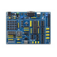
| Model | PIC-EK |
| Category | Motherboard |
| Language | English |