Page 8
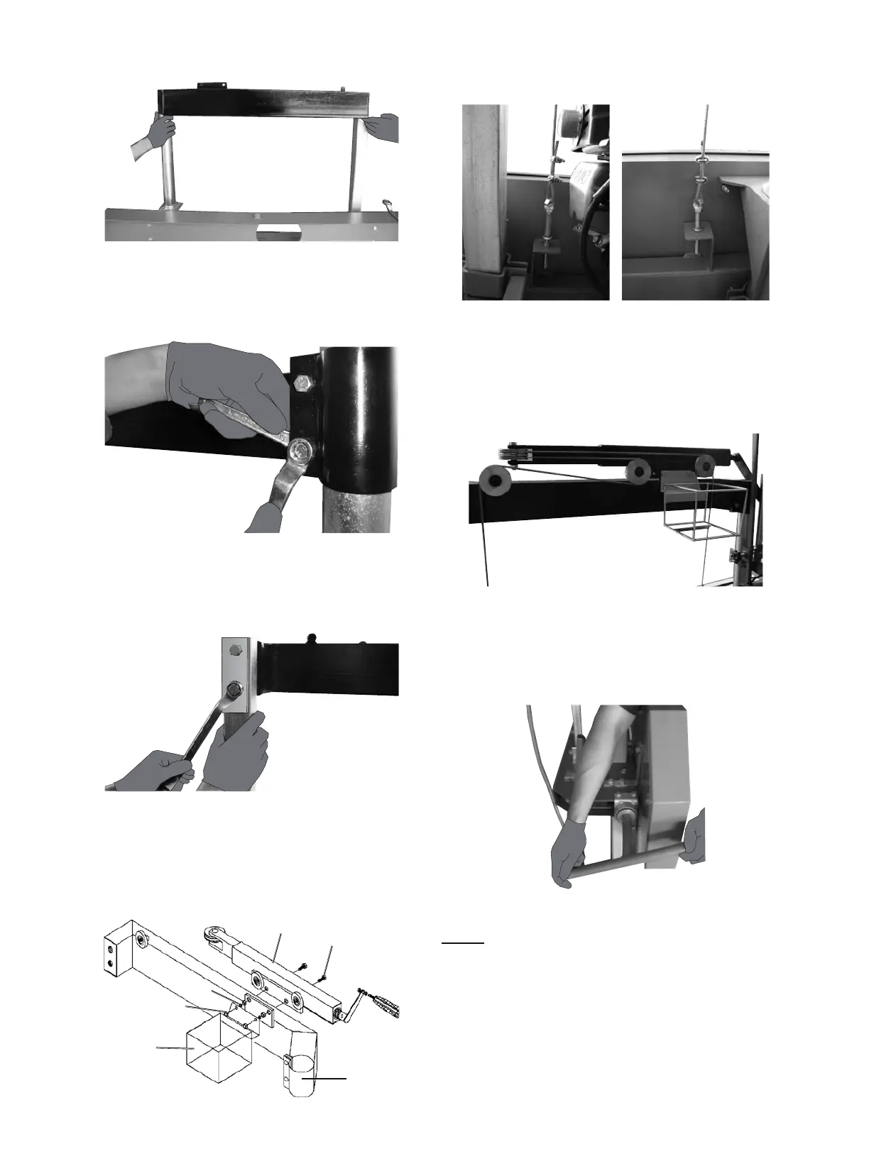
10. Place the Top Frame (23) on the Posts (20, 48).
Figure G: Top Frame
11. Secure the two Bolts (22) attaching
the Top Frame (23) to the
Round Post (20) as shown below.
Figure H: Top Frame Bolts
12. Attach the Top Frame (23) to the
Square Post (48) using the Bolts (49) and
Top Frame Brace (101) as shown below.
Figure I: Top Frame Bolts 2
13. Tighten the Bolts (8,58) and Nuts (5,9).
14. Attach the External Tube (34) and the Water Tank
Tray (45) to the Top Frame (23) using the Bolts (44),
Spring Washer (98), and Nut (99), as shown below.
44
34
23
45
98
99
15. Thread the Cable Anchor Bolts (46) into
the Blade Guard (50) as shown below.
Figure K: Cable Anchor Bolt Locations
16. Route Cables as shown below.
Hook the loops around the two posts on the
back of the External Tube (34). The lower cable
attaches to the lower post. Adjust the Cable
Anchor Bolts (46) until the two cables are equal.
Figure L: Cable Route
17. Loosen the Bolt (70) and the Fixed Block (71) to
move the Fixed Block away from the Blade. Rotate
the Tension Handle (14) in a clockwise direction
to properly tension the Blade, as shown below.
Figure M: Tension Handle
NOTE: Pull up on Blade at Center Guard.
$OORZIRUQRPRUHWKDQƎƎ
movement up or down (“give”) on the Blade.
7KHƎƎJLYHLQGLFDWHVSURSHU%ODGHWHQVLRQ
SAFETY OPERATION MAINTENANCEASSEMBLY
 Loading...