Page 7
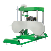
can move smoothly on the round post. Then secure
it in place with the Right Lock Handle (59).
Figure C: Right Lock Handle
Blade
Guard
(50)
Right
Lock
Handle
(59)
Round Post (20)
4. Slide the Square Post (48) into the Blade Guard,
as shown below. Adjust the bolts until it can
move smoothly on the square post. Then secure
it in place with the Left Lock Handle (54).
Figure D: Left Lock Handle
Blade
Guard (50)
Left Lock
Handle (54)
Square
Post
(48)
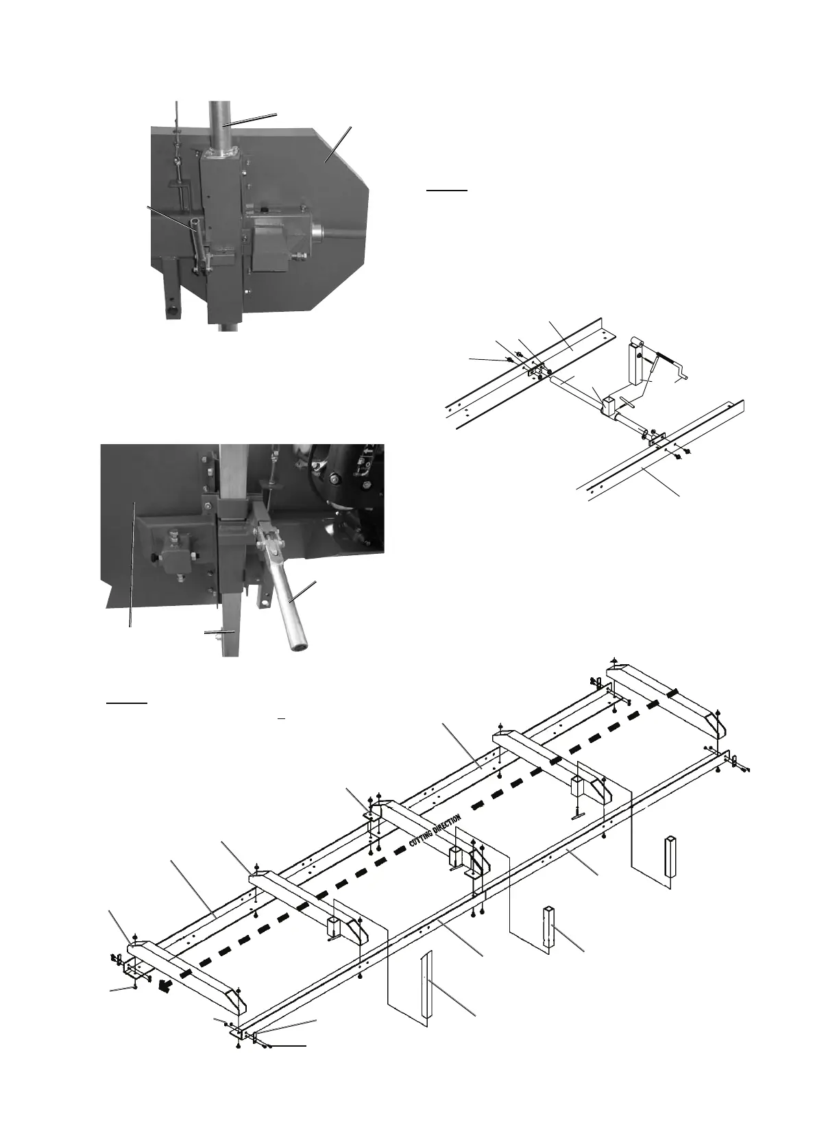
5. Lay out the Track sections (78, 92) as shown below.
6. Use the Bolts (22) and Nuts (25) to fasten the End
Stops (79) to the Track Sections, as shown below.
7. Use the Flange Bolts (77) and Flange
Nuts (84) to fasten the Center Support (90a)
and Middle Supports (81a) to the Track
Sections (78, 92), as shown below.
NOTE: The Track (78) and Track (92) must be aligned
not only on the top surface, but also on the side surface.
The gap between these two parts must be small.
If the top surface of the Tracks are not aligned, use
DJULQGHURU¿OHQRWLQFOXGHGWRVPRRWKWKHPRXW
8. Install the Rocker Tube (88) and Round
Tube (85) assembly as shown below.
Figure F: Rocker Tube
77
78
92
83
84
85
86a
87
89
88
9. Place the carriage onto the track.
Figure E: Track Assembly
NOTE: After assembly, the central distance
RIWKH7UDFNPXVWEHƎ+Ǝ
80a
77
78
79
81a
82
92
78
90a
91
92
Saw mill
¿QLVKHVFXW
at this end.
Saw mill
starts cut from
this end.
22
25
 Loading...