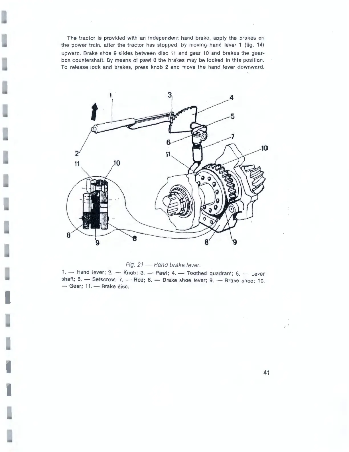
The tractor is provided with
an
independent hand brake, apply the brakes
on
the power train, after the tractor has stopped, by moving hand lever 1 (fig.
14)
upward. Brake shoe 9 slides between disc
11
and gear
10
and brakes the gear-
box countershaft. By means of pawl 3 the brakes may
be
locked
in
this position.
To
re
lease
lock
and brakes, press knob 2 and move the hand lever downward.
8
2
11
3
Fig. 21 -
Hand
brake
lever
.
1.
- Hand lever; 2. - Knob; 3. - Pawl;
4.
- Toothed quadrant;
5.
- Lever
shaft; 6. - Setscrew;
7.
- Rod; 8. - Brake shoe lever;
9.
- Brake shoe;
10
.
- Gear;
11
. - Brake disc.
41