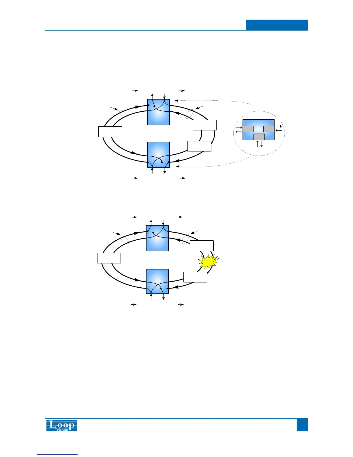
The diagram below illustrates the DS0 signal path in normal condition. The DS0 signal travels on both primary path and
secondary path. The primary path is configured to be the working path and the secondary path is configured to be the
protection path.
Secondary Path
E1
E1
1 * DS0 Input1 * DS0 Output
1 * DS0 Output1 * DS0 Input
E
O9500R
E1
C
O9500R
O9500R
(Protection Path)
Node A
O9500R
Node B
Protected DS0
3E1
Card
3E1
Card
O9500R
E1/V.35
Card
Node B Node A
Node B
Node A
Node B
Node A
Secondary Path
The diagram below illustrates the DS0 signal path in faulty condition. When the primary path is broken, the secondary path
will automatically become the working path.
E1
E1
1 * DS0 Input
1 * DS0 Output
1 * DS0 Output1 * DS0 Input
E
O9500R
D
O9500R
E1
Node B
O9500R
Node A
O9500R
(Working Path)
Primary Path
 Loading...