EasyManua.ls Logo

Loren Cook ACRU-B - User Manual

Default Icon
12 pages
Print Icon
To Next Page IconTo Next Page
Loading...
This publication contains the installation, operation and
maintenance instructions for standard units of the AC-
Centrifugal Roof and Wall Exhausters.
• ACE-D / ACE-B
ACW-D / ACW-B / ACW-HP / ACW-XP
ACRU-D / ACRU-B / ACRU-HP / ACRU-XP
Carefully read this publication and any
supplemental documents prior to any
installation or maintenance procedure.
Loren Cook AC catalog provides additional information
describing the equipment, fan performance, available
accessories, and specification data.
For additional safety information, refer to AMCA
publication 410-96, Safety Practices for Users and Installers
of Industrial and Commercial Fans.
All of the publications listed above can be obtained from
Loren Cook Company by phoning (417)869-6474,
extension 166; by FAX at (417)832-9431; or by e-mail at
info@lorencook.com.
For information and instructions on special equipment,
contact Loren Cook Company at 417.869-6474.
Receiving and Inspection
Immediately upon receipt of an AC fan, carefully inspect
the fan and accessories for damage and shortage.
• Turn the wheel by hand to ensure it turns freely and
does not bind.
• Check dampers (if included) for free operation of all
moving parts.
• Record on the Delivery Receipt any visible sign of
damage.
Rotating Parts & Electrical Shock Hazard:
Disconnect electric power before working on unit.
Follow proper lockout / tagout procedures to ensure
the unit cannot be energized while being installed or
serviced.
A disconnect switch should be placed near the fan in
order that the power can be swiftly cut off, in case of
an emergency and in order that maintenance
personnel are provided complete control of the power
source.
Grounding is required. All field-installed wiring must
be completed by qualified personnel. All field-
installed wiring must comply with National Electric
Code (NFPA 70) and all applicable local codes.
Failure to follow these instructions could result in
death or serious injury.
Centrifugal Roof and Wall Exhausters
INSTALLATION, OPERATION AND MAINTENANCE
Handling
Lift the fan by the shipping
carton or lifting lugs provided
under top cap. NOTICE! Never
lift by the shaft, motor or
housing.
Storage
If the fan is stored for any
length of time prior to installation,
store it in its original shipping
crate and protect it from dust,
debris and the weather.
Installation
If the fan was delivered with the motor unmounted, see
the maintenance section for belt and pulley installation.
If the fan was purchased as a wall mount unit and a
grease terminator or grease trough was not purchased, a 1-
1/16 inch diameter drain hole should be drilled at the bottom
side of the fan for drainage.
Code requirements and environmental effects
The attachment of roof mounted fans to the roof curb
as well as the attachment of roof curbs to the building
structure must exceed the structural requirements
based on the environmental loading derived from the
applicable building code for the site. The local code
official may require variations from the recognized
code based on local data. The licensed engineer of
record will be responsible for prescribing the correct
attachment based on construction materials, code
requirements and environmental effects specific to
the installation.
Failure to follow these instructions could result in
death or serious injury.
AC
Lifting Lugs
®
Question and Answer IconNeed help?

Do you have a question about the Loren Cook ACRU-B and is the answer not in the manual?

Summary

Installation, Operation and Maintenance

Handling

Lift the fan by the shipping carton or lifting lugs provided under top cap. Never lift by the shaft, motor or housing.

Storage

If the fan is stored for any length of time prior to installation, store it in its original shipping crate and protect it from dust, debris and the weather.

Installation Procedures

If the fan was delivered with the motor unmounted, see the maintenance section for belt and pulley installation.

WARNING: Rotating Parts & Electrical Shock Hazard

Disconnect electric power before working on unit. Follow proper lockout / tagout procedures to ensure the unit cannot be energized.

Receiving and Inspection

Immediately upon receipt of an AC fan, carefully inspect the fan and accessories for damage and shortage.

Wall Exhauster Installation and Wiring

Damper Installation

If your fan is supplied with dampers, follow the directions below. Ensure the damper will open freely for the correct direction of the airflow.

Wiring Installation and Safety

All wiring should be in accordance with local ordinances and the National Electrical Code, NFPA 70. Ensure power supply matches motor nameplate.

Final Steps, Operation, and Maintenance

Final Installation Steps

Ensure fasteners and set screws are tightened according to the recommended torque. Inspect for correct amperage and voltage.

Operation and Start-up

Lock out power sources. Inspect and tighten fasteners. Turn on fan at lowest speed, checking for rotation, vibration, noise.

Inspection Schedule

Inspect fan at 30 minute, 8 hour, and 24 hour intervals. Check bolts, belt alignment, and tension.

Maintenance Schedule

Establish a schedule for inspecting all parts of the fan based on operating conditions and location.

Bearings, Speed, and Pulleys

Fan Bearings and Lubrication

Fan bearings are prelubricated. Relubricate according to the conditions chart. Use NLGI #2 grease.

Motor Bearings and Lubrication

Motor bearings are prelubricated. Follow motor nameplate instructions or table for relubrication intervals.

Changing Fan Speed

Adjust variable pitch pulleys to change fan speed. Ensure RPM limits of fan and horsepower limits of motor are maintained.

Pulley and Wheel Procedures

Replacing Pulleys and Belts

Clean shafts, loosen setscrews, remove pulleys. Clean bores, place light oil, and reassemble. Ensure proper belt tension.

Pulley Alignment

Adjust pulley alignment by loosening setscrews and moving the motor pulley on the motor shaft.

Bearing Replacement

Remove old bearings, clean shaft, slide new bearings into position, and tighten securely. Do not tighten setscrews before bearing bolts.

Wheel Replacement

Drill and tap holes in the hub OD. Screw puller arms into tapped holes to back wheel off the shaft.

Wheel-to-Inlet Clearance and Troubleshooting

Wheel-to-Inlet Clearance

Critical for performance. Verify clearance before start-up. Adjust overlap by loosening wheel hub and moving wheel on shaft.

Troubleshooting Common Issues

Addresses problems like low capacity, excessive vibration, noise, and overheating of motor or bearings.

Parts Lists by Model

ACE-D Parts List

Detailed parts breakdown for ACE-D models, including sizes 70-100 and 120-180.

ACE-B Parts List

Detailed parts breakdown for ACE-B models, covering sizes 60-100 through 330-540.

ACW-D Parts List

Detailed parts breakdown for ACW-D models, including sizes 70-100 and 120-195.

ACW-B Parts List

Detailed parts breakdown for ACW-B models, covering sizes 100 through 180-245.

ACRU-D and ACRU-B Parts List

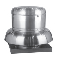
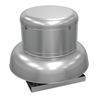
Parts breakdown for ACRU-D (sizes 70-100, 120-195) and ACRU-B (sizes 100-490) models.

Limited Warranty Information

Loren Cook Company Warranty

One-year warranty for manufacturing defects. Excludes shipping costs. Warranty void if fan is altered or misused.

Loren Cook ACRU-B Specifications

General IconGeneral
BrandLoren Cook
ModelACRU-B
CategoryFan
LanguageEnglish

Related product manuals