VARI-FLOW PRESSURE CONTROLLER IO&M
B51004-002
2
LOW pressure port
HIGH pressure port
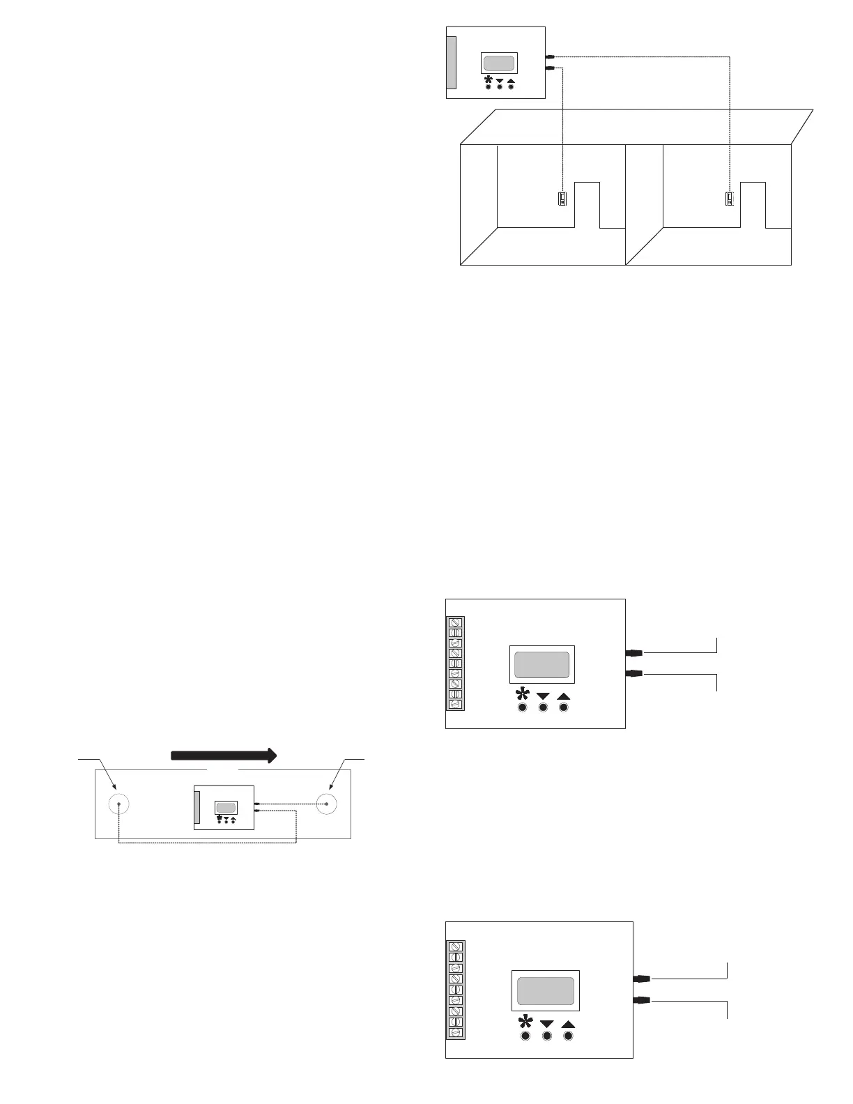
Static Pressure Control
• Place the Pressure Controller box as close as possible
to the pressure tap and fan. The location should be easy
to access.
• Keep the length of the wiring between control box and
the fan to 100 feet (30 m) or less.
• Keep the length of the pressure tubing between control
box and pressure taps to 50 feet (15 m) or less.
One Duct Tap
The One Duct Tap maintains a constant pressure in the
duct. The constant pressure is relative to ambient pressure of
space where the Pressure Controller is mounted. To connect
the One Duct Tap:
• Use a 1/8” (3.175 mm) tubing to connect between the
pressure tap and HIGH pressure port on the Pressure
Controller.
• Leave the LOW pressure port open to the atmosphere.
Com
24V~
Prs+
Rev
Dir
Ext
Kcom
Knc
Kno
Open to Atmosphere
Low Pressure Port
High Pressure Port
To Pressure Tap
1/8" (3.175 mm) Tubing
One Room Tap
The One Room Tap maintains a constant pressure in a
room. The constant pressure depends on the value of the
space pressure where the Pressure Controller is mounted.
To connect the One Room Tap:
• Use a 1/8” (3.175 mm) tubing to connect between the
pressure tap and HIGH pressure port on the Pressure
Controller.
• Leave the LOW pressure port open to the atmosphere.
Com
24V~
Prs+
Rev
Dir
Ext
Kcom
Knc
Kno
Open to Atmosphere
Low Pressure Port
High Pressure Port
To Pressure Tap
1/8" (3.175mm) Tubing
Duct Pressure
Location and Positioning
Obtaining optimum results from positioning the duct
pressure tap is dependent on the planning and layout of
the system.
• Install the pressure tap on a duct with a minimum of 1.5
duct diameters of straight duct. Place it away from any
damper, elbow, or other obstructions.
• Ensure that the pressure tap is placed toward the top of
a duct that runs horizontally. This minimizes condensa-
tion entering the tube.
• On a rectangular duct mount, place the pressure tap
away from the corners.
• On a stack system, place the pressure tap at a distance
of one-third from the bottom of the duct.
Installation
• Remove any exterior insulation. If required, insulation
could be replaced after the installation.
• Drill a 3/8” (9.525 mm) hole in the duct where the pres-
sure tap should be installed.
• Place the 6” (152 mm) tube into the hole and move the
mounting base up to the duct in any orientation.
• On a round duct, rotate the tap so that the mounting
holes are aligned with the duct.
• Attach the duct pressure tap to the duct using self-drill-
ing zip screws, tting in the gasket evenly.
• Attach the tubing from the barbed port to the pressure
controller.
Duct Velocity or Air Volume
Location and Positioning
Obtaining optimum results from positioning the pressure
taps is dependent on the planning and layout of the system.
• If you are using total and static probe to measure velocity
pressure, mount the pressure taps in close proximity to
each other but in such a way so as not to interfere with
each other. For this, select a spot in the duct that is at
least 5 duct diameters away from any obstructions such
as elbows, dampers, transitions, or diusers.
Static
Pressure Tap
Low Pressure Port
High Pressure Port
Duct
Total
Pressure Tap
Air Flow
Room Pressure
• Identify the area(s) in which you intend to control the
static pressure.
• Mount the pressure tap near the center of the zone that
you intend to measure.
• Do not mount the pressure tap in an enclosed area such
as a closet and areas that are prone to drafts.
 Loading...