3
VARI-FLOW PRESSURE CONTROLLER IO&M
B51004-002
Two Room Taps
The Two Room Taps maintain a constant dierential pres-
sure between two rooms. This constant dierential pressure
enables the controller to monitor and regulate the pressure
through the Pressure Controller when placed at a remote lo-
cation. To connect the Two Room Taps:
• Use a 1/8” (3.175 mm) tubing to connect between the
pressure tap in the high pressure room and the HIGH
pressure port on the Pressure Controller.
• Use a 1/8” (3.175 mm) tubing to connect between the
pressure tap in the low pressure room and the LOW
pressure port on the Pressure Controller.
Com
24V~
Prs +
Rev
Dir
Ext
Kcom
Knc
Kno
Static Pressure Tap
Low Pressure Port
High Pressure Port
Total Pressure Tap
1/8" (3.175mm) Tubing
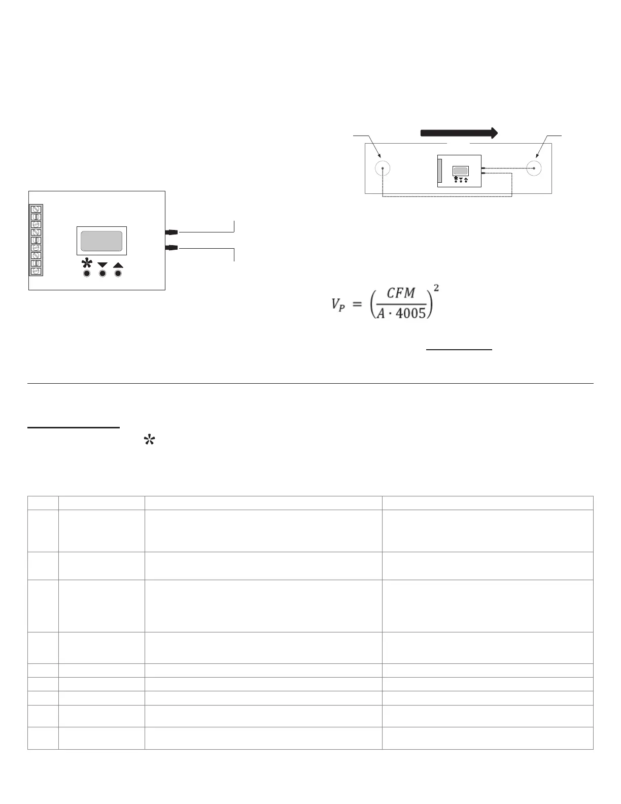
Velocity Pressure Control
One Duct Static Tap and One Duct Total Tap
The One Duct Static Tap and One Duct Total Tap maintain
a constant velocity pressure in a duct. This constant velocity
pressure enables the controller to modulate the airow auto-
matically to compensate for lter or coil loading. To connect
the Duct Static and Total Tap:
• Use a 1/8” (3.175 mm) tubing to connect between the
total pressure tap and HIGH pressure port on the Pres-
sure Controller.
• Use a 1/8” (3.175 mm) tubing to connect between the
static pressure tap and LOW pressure port.
Static
Pressure Tap
Low Pressure Port
High Pressure Port
Duct
Total
Pressure Tap
Air Flow
In this conguration, the Pressure Controller maintains a
velocity pressure by measuring and maintaining the dier-
ence between total and static pressure read at the HIGH and
LOW pressure ports. To set up the controller, calculate the
required velocity pressure based on the intended CFM and
duct area using the following formula:
where A is the duct area in ft
2
Set the desired pressure setpoint parameters from the Pro-
gramming menu (see Programming). To verify the airow
calculation, take external CFM measurements and calculate
the velocity pressure until the desired airow is achieved.
Step
Display Description Values
1
Pr:X.XXX
Sp:X.XX
Operation Mode & Setpoint Adjustment
When 24 Vac is supplied to the unit, the SPC displays the actual
pressure (Pr) and the setpoint of the static pressure (Sp). Use the arrow
keys to change the setpoint.
Increments of 0.01
Units - in w.c. (inches of water column)
Range - 0.00 to 1.99
2
Deadband
(range: 0.000-0.243)
Deadband Adjustment
Not generally important for EC motor control
Default: 0.014 (SPC 1.0), 0.0014 (SPC 0.1)
Increment: 0.005 (SPC 1.0), 0.0005 (SPC 0.1)
3
Response Speed:
(range: 1-25)
Response Speed Adjustment
Prevents unjustied changes due to a temporary surge of static
pressure, which could aect the system. To increase system stability,
we recommended setting the Response Speed to lower end of range
(setting 1 or 2).
1 to 25 (factory setting: #2)
1 lowest: (100 mV/sec, 100 seconds for a 0-10 Vdc output).
25 fastest: (1.78 V/sec, 5.6 seconds for 0-10 Vdc output).
4
Cntl Out
Output Signal Adjustment
The conguration of the output signal applies to both direct acting and
reverse acting.
▲ or ▼ = 0-10 Vdc / 2-10 Vdc
5
Direct Act: Direct acting output conguration ▲ or ▼ = Vdc or mA (Set to Vdc for EC motor control)
6
Reverse Act: Reverse acting output conguration ▲ or ▼ = Vdc or mA (Set to Vdc for EC motor control)
7
Contact: Relay conguration Direct or Reverse
8
Contact On: Relay SETPOINT (Sp) to come ON Contact Direct: 0.31-2.00 ”wc Contact Reverse: 0.00-0.31 ”wc
9
Contact O: Relay SETPOINT (Sp) to turn OFF Contact Direct: 0.00-0.31 ”wc Contact Reverse: 0.31-2.00 ”wc
Programming
Press the menu button
to enter programming mode. Once in programming mode, the menu button always advances to
the next step. Use the arrow keys to change the value of the current menu item. Press and hold an arrow key to scroll rapidly
through the values. Changes are automatically saved. The Vari-Flow Pressure Controller automatically exits the menu after 20
seconds of inactivity.
 Loading...