Do you have a question about the LOTOS MIG140 and is the answer not in the manual?
Hazards and precautions regarding electrical shock during operation and maintenance.
Risks from welding fumes/gases and requirements for ventilation and respiratory protection.
Potential interference of EMF fields with medical devices and unknown health effects.
Dangers of arc rays and infrared radiation to eyes and skin; need for protective gear.
Precautions to prevent fires and explosions, including hazard removal and fire extinguishers.
Safe handling, storage, and securing of compressed gas cylinders to prevent damage or explosion.
Safety measures for electrical equipment, including power disconnection and grounding.
Warnings about moving parts and the importance of keeping guards closed and secure.
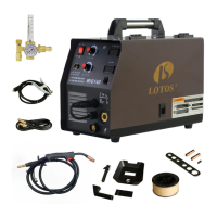
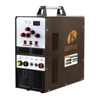
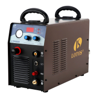
Overview of the LOTOS MIG140 welder's features, capabilities, and target users.
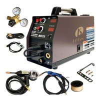
List of all components and accessories provided with the MIG140 welder package.
Technical data on input voltage, output power, dimensions, weight, and duty cycle.
Identification and brief explanation of the controls and connectors on the front panel.
Identification of key components located on the side of the welding machine.
Identification of components and fittings found on the rear panel of the welder.
Guidelines for selecting a suitable operating location and general machine preparation.
Detailed steps for correctly connecting the ground clamp to the welding machine.
Instructions for connecting the welding gun and its control wire to the machine.
Procedure for installing or reversing the wire drive roll for different wire sizes.
Steps for installing 8" and 4" wire spools, including spindle adapter removal.
Steps for connecting the compressed gas cylinder, regulator, and supply hose.
Essential safety warnings and precautions to follow during welding operations.
Sequential steps for preparing the machine and welding gun before starting.
Detailed procedure for performing welding, including gun control and positioning.
Information on the circuit breaker and thermostat overload protection for the power supply.
Explanation of the thermal protector, duty cycle, and automatic cooling fan operation.
Details on the two automatic circuits protecting the wire feeder motor from overload.
| Output Amperage | 140A |
|---|---|
| Output Current Range | 30A - 140A |
| Protection Class | IP21S |
| Welding Process | MIG |
| Input Current | 21A |
| Applicable Wire Diameter | 0.6-0.8mm |