I610 GB I 07 19 31100447
1
WARNING!
– Carefully read the manual before the installation or use.
– This equipment is to be installed by qualified personnel, complying to current standards, to avoid damages or safety
hazards.
– Remove eventual dangerous voltage from the product before any maintenance operation on it.
– The manufacturer cannot be held responsible for electrical safety in case of improper use of the equipment.
– Products illustrated herein are subject to alteration and changes without prior notice. Technical data and descriptions
in the documentation are accurate, to the best of our knowledge, but no liabilities for errors, omissions or
contingencies arising therefrom are accepted.
– A circuit breaker must be included in the electrical installation of the building. It must be installed close by the
equipment and within easy reach of the operator.
It must be marked as the disconnecting device of the equipment: IEC /EN 61010-1 § 6.11.
– Fit the instrument in an enclosure or cabinet with minimum IP51 degree protection.
– Clean the instrument with a soft dry cloth, do not use abrasives, liquid detergents or solvents.
INTRODUCTION
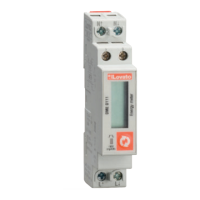
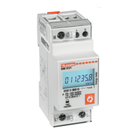
The DME D111 is a single-phase active and reactive energy meter for direct connection, for currents up to 40A, equipped
with a built-in RS485 serial interface.
The energy accuracy is compliant with standard IEC/EN 62053-21 class 1.
Apart from energy metering, it can measure additional indications, for a total of 14 measurements that can be visualized
on the LCD display.
The DME D111 has a standard 1U (18mm wide) modular housing and is supplied with sealable terminal blocks.
DESCRIPTION
– Modular DIN-rail housing, 1U (18mm wide).
– Direct connection for currents up to 40A.
– Active energy measure complies IEC/EN 62053-21 class 1.
– Counter with 5+1 digits.
– Button for measure selection and programming.
– Total active and reactive energy meters.
– Partial active and reactive energy meters, resettable.
– Hour counter, total and partial.
– Pulse LED for active energy consumption.
– Indication of instantaneous consumption (active power).
– RS485 interface with Modbus-RTU and ASCII protocols.
SELECTION OF READINGS
– Pressing briefly the button it is possible to select the readings on the display, following the sequence in the table
reported below.
– Each measure is indicated by the correspondent icon in the higher part of the display.
– After one minute has elapsed after the last keystroke, the display moves automatically back to the total active energy
screen.
ATTENZIONE!!
– Leggere attentamente il manuale prima dell’utilizzo e l’installazione.
– Questi apparecchi devono essere installati da personale qualificato, nel rispetto delle vigenti normative impiantistiche,
allo scopo di evitare danni a persone o cose.
– Prima di qualsiasi intervento sull’apparecchio, rimuovere eventuali tensioni pericolose dall’apparecchio
– Il costruttore non si assume responsabilità in merito alla sicurezza elettrica in caso di utilizzo improprio del dispositivo.
– I prodotti descritti in questo documento sono suscettibili in qualsiasi momento di evoluzioni o di modifiche. Le
descrizioni ed i dati a catalogo non possono pertanto avere alcun valore contrattuale.
– Un interruttore o disgiuntore va compreso nell’impianto elettrico dell’edificio. Esso deve trovarsi in stretta vicinanza
dell’apparecchio ed essere facilmente raggiungibile da parte dell’operatore. Deve essere marchiato come il dispositivo
di interruzione dell’apparecchio: IEC/ EN 61010-1 § 6.11.
– Installare lo strumento in contenitore e/o quadro elettrico con grado di protezione minima IP51.
– Pulire lo strumento con panno morbido, non usare prodotti abrasivi, detergenti liquidi o solventi.
INTRODUZIONE
Il DME D111 è un contatore di energia monofase per inserzione diretta, per correnti fino a 40A, dotato di interfaccia seriale
RS485.
La misurazione dell’energia è conforme alla norma IEC/EN 62053-21 classe 1.
Oltre alla misurazione dell’energia, è in grado di fornire ulteriori indicazioni, per un totale di 14 misure, che possono essere
visualizzate sull’ampio display LCD.
Il DME D111 ha un contenitore modulare standard di larghezza 1U (18mm) ed è fornito di serie di coprimorsetti
piombabili.
DESCRIZIONE
– Esecuzione modulare 1U (18mm) per guida DIN.
– Inserzione diretta per correnti max 40A.
– Misura energia attiva conforme a IEC/EN 62053-21 classe 1.
– Contatore con 5+1 cifre.
– Tasto per la selezione delle misure e programmazione.
– Contatori di energia attiva e reattiva totali.
– Contatori di energia parziali azzerabili.
– Contaore totale e parziale.
– LED frontale a impulsi per energia attiva consumata.
– Indicazione consumo istantaneo (potenza attiva).
– Interfaccia RS485 con protocollo Modbus-RTU e ASCII.
SELEZIONE MISURE
– Premendo brevemente il pulsante è possibile selezionare le misure sul display dello strumento, secondo la
sequenza indicata nella tabella riportata sotto.
– A ciascuna selezione corrisponde un’icona nella parte alta del display, con l’unità di misura selezionata.
– Dopo un minuto senza premere il pulsante frontale, la misura si riposiziona sul contatore totale di energia attiva.
Icon Measurement Format
kWh Total active energy 00000,0
kWh + Part Partial active energy 00000,0
kvarh Total reactive energy 00000,0
kvarh + Part Partial reactive energy 00000,0
V Voltage 000,0
A Current 00,00
kW Active power 00,00
kvar Reactive power 00,00
PF Power factor 0,00
Hz Frequency 00,0
h Hour counter (hhhhh.mm) 0000,00
h + Part Partial hour counter (hhhhh.mm) 0000,00
kW +d Average active power (15 min demand) 00,00
kW+d+▲ Max avg. active power (max demand) 00,00
Icona Misura Formato
kWh Energia attiva totale 00000,0
kWh + Part Energia attiva parziale 00000,0
kvarh Energia reattiva totale 00000,0
kvarh + Part Energia reattiva parziale 00000,0
V Tensione 000,0
A Corrente 00,00
kW Potenza attiva 00,00
kvar Potenza reattiva 00,00
PF Fattore di potenza 0,00
Hz Frequenza 00,0
h Contaore (hhhhh.mm) 0000,00
h + Part Contaore parziale (hhhhh.mm) 0000,00
kW +d Potenza attiva media (demand su 15 min) 00,00
kW+ d +▲ Max potenza attiva media (max demand) 00,00
These measurements are shown only enabling parameter P-08.
These measurements are shown only enabling parameter P-09.
Queste misure sono visibili solo abilitando il parametro P-08.
Queste misure sono visibili solo abilitando il parametro P-09.
DME D111
GB
CONTATORE DI ENERGIA MONOFASE A INSERZIONE DIRETTA CON INTERFACCIA RS485
Manuale di installazione
I
LOVATO ELECTRIC S.P.A.
24020 GORLE (BERGAMO) ITALIA
VIA DON E. MAZZA, 12
TEL. 035 4282111
E-mail info@
L
ovato
E
lectric.com
Web www.
L
ovato
E
lectric.com
SINGLE-PHASE DIRECT CONNECTION ENERGY METER WITH RS485 INTERFACE
Installation manual
METROLOGICAL LED
– The red LED on the front emits 1000 pulses for every kWh of consumed Energy (that is, one pulse every Wh).
– The pulsing frequency of the LED gives an immediate indication of the energy flowing in every moment.
– The pulse duration, LED colour and intensity are compliant with the reference standards that define its utilization in
order to verify the accuracy of the energy meter.
RS485 INTERFACE
– Via the RS485 interface the value of energy meters and can be read from DME D111 as well as all other measures.
– The device acts as a standard Modbus slave.
– The configuration of the serial communication is done with the setup parameters from P-20 to P-24.
– The map of the measures on the Modbus protocol is shown in the following Modbus address table chapter.
For a more detailed description, see technical instruction I315 (downloadable from website www.LovatoElectric.com).
– For wiring diagrams, see the end of this manual.
PROGRAMMABLE LIMIT THRESHOLD
– Through parameters from P-02 to P-07 it is possible to define the behaviour of a programmable limit threshold, whose
status can be read from the communication protocol (see modbus addresses table).
– The programmable limit threshold can be used for instance to signal alarm situation to a remote device.
– Note: during parameter setting (setup) the status of the programmable limit threshold is not updated.
INCORRECT WIRING INDICATION
– In case of incorrect wiring, when the device detects a reverse energy flow, the display shows the blinking code Error 3.
– This error is caused by either reverse connection of current wires (terminals L↑ and L↓) or reverse voltage wiring
(terminals N - L↑).
– In these conditions, the energy is not counted.
LED METROLOGICO FRONTALE
– Il LED rosso frontale emette 1000 impulsi per ogni kWh di energia consumata (ovvero 1 impulso per ogni Wh).
– La frequenza di lampeggio del LED dà una immediata indicazione dell’entità della potenza richiesta in un determinato
istante.
– La durata del lampeggio, il colore e l’intensità del LED sono conformi alle norme che prescrivono il suo utilizzo ai fini
di una verifica metrologica della accuratezza del contatore di energia.
INTERFACCIA RS485
– Tramite l’interfaccia RS485 è possibile leggere dal DME D111 sia il valore dei contatori di energia sia tutte le altre
misure.
– L’apparecchio si comporta come uno slave Modbus standard.
– La parametrizzazione della comunicazione seriale si effettua con i parametri di setup da P-20 a P-24.
– La mappa delle misure sul protocollo Modbus è riportata nel seguente capitolo Tabella indirizzi Modbus.
Per una descrizione più particolareggiata, vedere l’istruzione tecnica I315 (scaricabile dal sito internet
www.LovatoElectric.com).
– Per gli schemi di collegamento vedere alla fine del presente manuale.
SOGLIA LIMITE PROGRAMMABILE
– Tramite i parametri da P-02 a P-07 è possibile definire il comportamento di una soglia limite programmabile, il cui
stato può essere letto tramite il protocollo di comunicazione (vedere tabella indirizzi Modbus).
– La soglia limite programmabile può essere utilizzata ad esempio per segnalazioni di allarme da remoto.
– Nota: durante l’impostazione dei parametri (setup) lo stato della soglia limite programmabile non viene aggiornato.
INDICAZIONE DI COLLEGAMENTO ERRATO
– In caso di collegamento errato, quando l’apparecchio rileva un flusso di energia di direzione contraria, viene attivata
l’indicazione lampeggiante Error 3.
– Questo errore può essere provocato dalla inversione del collegamento della corrente (morsetti L↑ e L↓) oppure dalla
inversione dei morsetti della tensione (N - L↑).
– In queste condizioni l’energia non viene conteggiata.