DMK21-22-51-52_PLGB 27/04/2005 Str. 1/7
PL
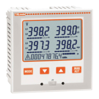
MIERNIK CYFROWY DIGITAL MULTIMETER
DMK21-22 -51-52 DMK21-22-51-52
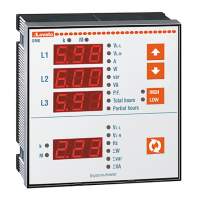
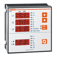
DMK2…
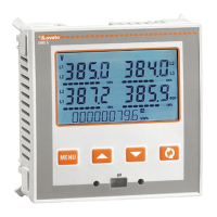
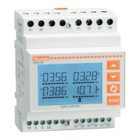
DMK5…
Przykład ustawiania przekładni
150 (750 / 5).
Przykład ustawiania filtru uśredniania
na wartość 3.
OPIS
• Wersja tablicowa, obudowa 96x96 lub modułowa.
• 4 wyświetlacze LED o wysokiej dokładności.
• Łatwa instalacja i ustawienia.
• Pomiar RMS (TRMS).
• 47 pomiary i funkcja analizatora sieci.
• Pomiary energii czynnej i biernej
• Pomiar energii w dwóch kwadrantach
• Zapis wartości max i min.
Tylko wersja DMK22 /DMK52
• Izolowany port RS485
• Protokoły komunikacyjne MODBUS RTU i ASCII
• 7 pomiarów dostępnych przez MODBUS (RS485)
- Max zapotrzebowanie
- Piki prądowe z 3 faz
- Asymetria napięcia
- Niesymetryczność prądu w systemie
USTAWIENIA PARAMETRÓW
• Naciśnij jednocześnie przyciski C i D przez 5 sekund
by uzyskać dostęp do ustawień
• Wyświetlacz DISPLAY 1 pokaże P.01 co oznacza,
że wybrany do ustawiania został parametr 01.
• Wyświetlacz DISPLAY 2 i 3 pokaże wartość
zaprogramowaną dla wybranego parametru.
• Przyciskami A i B zwiększamy lub zmniejszamy
wartość wybranego parametru.
• Przyciskami C i D wybieramy parametry od P.01
do P.25.
• Naciskając przycisk D przez 2 sekundy
zapamiętujemy ustawienia i wychodzimy.
• Normalnie, by urządzenie zaczęło działać,
ustawiamy tylko parametr P.01, pozostałe
zostawiamy jako domyślne, ustawione fabrycznie.
TABELA PARAMETRÓW
2 fazy
3 fazy
2ph
3ph
1-2-3
P.07 Czas pow. do wst.
ust. wyświetlacza
P.11 Czas całkowania
max zapotrzeb.
P.41 Adresy
P.42
Transmisja danych
4800,9600,19200
9600
P.43
Pa
rzystość
1 - parzysty
0
P.44
Pr
otokoły
1
P.45
Modem
automatycznie
0
Uwaga! Miernik może mierzyć moce do wartości
40MVA .
• By ustawić wartość parametru P.01 na 5-cyfr ±0,1
użyj razem wyświetlaczy 2 i 3.
• P.02 pozwala zmienić efekt stabilizacji funkcji
uśredniania używanej do pomiarów
DESCRIPTION
• Flush-mount 96x96mm housing and modular version.
• 4 LED displays for excellent readability
• Easy to install and configure
• RMS measures (TRMS)
• 47 measures and power analyzer functions
• Active and reactive energy meters
• Energy measure in two quadrants
• Minimum and maximum values logging.
For DMK22 and DMK52 versions only
• Opto-isolated RS485 communication interface
• Modbus RTU and ASCII communication protocols
• 7 measures available on Modbus (RS485) only:
- Maximum demand
- Peak current of 3 phases
- Voltage asymmetry
- System current unbalance
PARAMETER SETTING
• Press keys C and D together for 5 seconds to access
setting facility.
• DISPLAY 1 will show P.01 meaning that the setting for
parameter 01 has been chosen.
• With DISPLAYS 2 and 3, the value programmed for the
selected parameter is viewed.
• Keys A and B respectively increase and decrease the
value of that selected parameter.
• With keys C and D, parameters P.01 to P.25 can be
selected.
• Press key D for 2 seconds to store the setting and exit.
• Normally , to set the device working, parameter P0.1 only
must be set, eventually leaving the others at the default
value.
PARAMETER TABLE
connection
2 phases
3 phases
3 bala. pha
2ph
3ph
3bl
1-2-3
Max demand
integration time
Baud rate
4800,9600,19200
9600
Parity
1 - Even
2 - Odd
0
Protocol
1 - RTU
1
Modem
0 -
no auto
response
1 –
auto response
0
Note! The DMK calculating system can handle total power
values of up 40 MVA.
• To set the value of parameter P.01, a 5-digit+1-decimal
value is viewed using DISPLAYS 2 and 3 together.
• P.02 consents to change the stabilising effect of the
average function applied to the measurements.