I132 I GB F E 08 13 31100023
1
LOVATO ELECTRIC S.P.A.
24020 GORLE (BERGAMO) ITALIA
VIA DON E. MAZZA, 12
TEL. 035 4282111
TELEFAX (Nazionale): 035 4282200
TELEFAX (International): +39 035 4282400
E-mail info@
LovatoElectric.com
Web www.
LovatoElectric.com
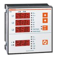
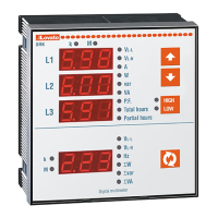
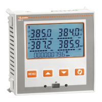
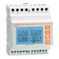
DMK 20 - DMK 50
I MULTIMETRI DIGITALI
GB DIGITAL MULTIMETERS
F MULTIMETRES NUMERIQUES
E MULTÍMETROS DIGITALES
DESCRIZIONE
– Dimensioni compatte 96x96mm e
modulare.
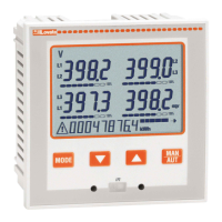
– 4 display a LED per una ottima leggibilità.
– Semplicità di installazione e
configurazione.
– Misure in vero valore efficace (TRMS).
– 47 misure con funzioni di analizzatore di
potenza.
– Memorizzazione di massimi e minimi.
IMPOSTAZIONE DEI PARAMETRI
– Premere contemporaneamente i pulsanti
C e D per 5 secondi per accedere alla
impostazione.
– Sul DISPLAY 1 comparirà P.01 ad
indicare che e’ stata selezionata
l’impostazione del parametro 01.
– Sui DISPLAY 2 e 3 verrà visualizzato il
valore attuale del parametro.
– I tasti A e B aumentano / diminuiscono il
valore del parametro attualmente
selezionato.
– I tasti C e D selezionano il parametro da
P.01 a P.10.
– Premere il tasto D per 2 secondi per
memorizzare ed uscire dalla
impostazione.
– Normalmente per rendere operativo lo
strumento e’ necessario impostare il solo
parametro P.01, lasciando gli altri
parametri al valore di default.
DESCRIPTION
– Compact 96x96mm size and modular
version.
– 4 LED displays for excellent readability.
– Easy to install and configure.
– Measurements in true RMS (TRMS).
– 47 measurements with power analyser
functions.
– Maximum and minimum measurement
recording.
PARAMETER SETTING
– Press buttons C and D together for 5
seconds to access setting.
– DISPLAY 1 will show P.01 meaning that
the setting for parameter 01 has been
chosen.
– DISPLAYS 2 and 3 will show the current
value of the parameter.
– Buttons A and B increase / decrease the
value of the currently selected parameter.
– Buttons C and D select parameter from
P.01 to P.10.
– Press button D for 2 seconds to store the
setting and exit.
– Normally, to set the instrument working it
is necessary to set parameter P.01 only,
leaving the other parameters at the
default value.
DESCRIPTION
– Dimensions compactes 96x96mm et type
modulaire.
– 4 afficheurs à DEL pour une bonne
lisibilité.
– Installation et configuration faciles.
– Mesures en valeur efficace vraie (TRMS).
– 47 mesures avec des fonctions
d’analyseur de puissance.
– Enregistrement des valeurs minimales et
maximales.
REGLAGES DES PARAMETRES
– Pour régler les paramètres, appuyez
simultanément sur les touches C et D
pendant 5 secondes.
– L’afficheur 1 (DISPLAY) indique P.O1 :
c’est le paramètre 01 qui est sélectionné.
– Les afficheurs 2 et 3 indiquent la valeur
du paramètre sélectionné.
– Les touches A et B permettent
d’augmenter/diminuer la valeur de ce
paramètre.
– Utilisez les touches C et D pour
sélectionner le paramètre P.O1 à P.1O.
– Pour enregistrer les paramètres et quitter
le menu, appuyez sur la touche D
pendant 2 secondes.
– Pour que l’instrument fonctionne, il faut
régler uniquement le paramètre P.01 et
laisser la valeur par défaut qui a été
assignée aux autres paramètres.
DESCRIPCION
– Dimensiones compactas 96x96mm y
modular.
– 4 displays de LED para una visualización
óptima.
– Simple instalación y configuración.
– Medida del verdadero valor eficaz
(TRMS).
– 47 medidas con funciones de analizador
de potencia.
– Memorización de máximos y mínimos.
CONFIGURACION DE PARAMETROS
– Para acceder al menú de configuración
de parámetros, presione
simultáneamente las teclas C y D durante
5 segundos.
– El DISPLAY 1 mostrará P.01 indicando
que el parámetro P.01 ha sido
seleccionado.
– Los DISPLAY 2 y 3 mostrarán los valores
del parámetro seleccionado.
– Los botones A y B aumentan o
disminuyen respectivamente el valor del
parámetro seleccionado.
– Use los botones C y D para seleccionar
los parámetros de P.01 a P.10.
– Pulse el botón D durante 2 segundos
para memorizar y salir de la
configuración.
– Normalmente, para hacer operativo el
aparato es necesario ajustar el parámetro
P.01, manteniendo los demás parámetros
predefinidos ajustados de fábrica.
Esempio impostazione rapporto TA: TA 1000/5A settare P01=200.
Example of CT ratio programming: with 1000/5A CT, set P01 to 200.
Exemple du réglage rapport TI : avec TI 1000/5A, réglez P01 à 200.
Ejemplo de programación de relación de TC: Con un TC de 1000/5A,
ajustar P01 a 200.
Esempio impostazione rapporto TA: TA 1000/5A settare P01=200.
Example of CT ratio programming: with 1000/5A CT, set P01 to 200.
Exemple du réglage rapport TI : avec TI 1000/5A, réglez P01 à 200.
Ejemplo de programación de relación de TC: Con un TC de 1000/5A,
ajustar P01 a 200.
Esempio impostazione tempo filtro average 3.
Example of average filter 3 setting.
Exemple de réglage du temps de filtre “Average” 3.
Ejemplo impostacíon tiempo filtro integrador 3.
DMK 20 DMK 50
Esempio impostazione tempo filtro average 3.
Example of average filter 3 setting.
Exemple de réglage du temps de filtre “Average” 3.
Ejemplo impostacíon tiempo filtro integrador 3.
DMK 20
DMK 50