EasyManua.ls Logo

LOVATO ELECTRIC PMVF 80 User Manual

LOVATO ELECTRIC PMVF 80
12 pages
To Next Page IconTo Next Page
Page #1 background imageLoading...
Page #1 background image
I634 GB 09 20 31100471
1
LOVATO ELECTRIC S.P.A.
24020 GORLE (BERGAMO) ITALIA
VIA DON E. MAZZA, 12
TEL. 035 4282111
E-mail info@
LovatoElectric.com
Web www.
LovatoElectric.com
PMVF 80
INTERFACE PROTECTION SYSTEM
Compliant with
VDE-AR-N 4105 and VDE V 0126-1-1
application guides
Instruction manual
GB
W
ARNING!
Carefully read the manual before the installation or use.
This equipment is to be installed by qualified personnel, complying to current standards, to avoid
damages or safety hazards.
Before any maintenance operation on the device, remove all the voltages from measuring and supply inputs and short-
c
ircuit the CT input terminals.
The manufacturer cannot be held responsible for electrical safety in case of improper use of the equipment.
Products illustrated herein are subject to alteration and changes without prior notice. Technical data and descriptions
in the documentation are accurate, to the best of our knowledge, but no liabilities for errors, omissions or
contingencies arising there from are accepted.
A circuit breaker must be included in the electrical installation of the building. It must be installed close by the
equipment and within easy reach of the operator. It must be marked as the disconnecting device of the equipment:
IEC /EN 61010-1 § 6.11.2.
Clean the device with a soft dry cloth; do not use abrasives, liquid detergents or solvents.
A
TTENZIONE!
Leggere attentamente il manuale prima dell’utilizzo e l’installazione.
Questi apparecchi devono essere installati da personale qualificato, nel rispetto delle vigenti normative
impiantistiche, allo scopo di evitare danni a persone o cose.
Prima di qualsiasi intervento sullo strumento, togliere tensione dagli ingressi di misura e di alimentazione e
c
ortocircuitare i trasformatori di corrente.
Il costruttore non si assume responsabilità in merito alla sicurezza elettrica in caso di utilizzo improprio del dispositivo.
I prodotti descritti in questo documento sono suscettibili in qualsiasi momento di evoluzioni o di modifiche. Le
descrizioni ed i dati a catalogo non possono pertanto avere alcun valore contrattuale.
Un interruttore o disgiuntore va compreso nell’impianto elettrico dell’edificio. Esso deve trovarsi in stretta vicinanza
dell’apparecchio ed essere facilmente raggiungibile da parte dell’operatore. Deve essere marchiato come il dispositivo
di interruzione dell’apparecchio: IEC/ EN 61010-1 § 6.11.2.
Pulire l’apparecchio con panno morbido, non usare prodotti abrasivi, detergenti liquidi o solventi.
ATTENTION !
Lire attentivement le manuel avant toute utilisation et installation.
Ces appareils doivent être installés par un personnel qualifié, conformément aux normes en vigueur en
matière d'installations, afin d'éviter de causer des dommages à des personnes ou choses.
Avant toute intervention sur l'instrument, mettre les entrées de mesure et d'alimentation hors tension et court-circuiter
les transformateurs de courant.
Le constructeur n'assume aucune responsabilité quant à la sécurité électrique en cas d'utilisation impropre du
d
ispositif.
Les produits décrits dans ce document sont susceptibles d'évoluer ou de subir des modifications à n'importe quel
m
oment. Les descriptions et caractéristiques techniques du catalogue ne peuvent donc avoir aucune valeur
contractuelle.
Un interrupteur ou disjoncteur doit être inclus dans l'installation électrique du bâtiment. Celui-ci doit se trouver tout
p
rès de l'appareil et l'opérateur doit pouvoir y accéder facilement. Il doit être marqué comme le dispositif
d
'interruption de l'appareil : IEC/ EN 61010-1 § 6.11.2.
Nettoyer l’appareil avec un chiffon doux, ne pas utiliser de produits abrasifs, détergents liquides ou solvants.
UWAGA!
Przed użyciem i instalacją urządzenia należy uważnie przeczytać niniejszą instrukcję.
W celu uniknięcia obrażeń osób lub uszkodzenia mienia tego typu urządzenia muszą być instalowane przez
wykwalifikowany personel, zgodnie z obowiązującymi przepisami.
Przed rozpoczęciem jakichkolwiek prac na urządzeniu należy odłączyć napięcie od wejść pomiarowych i zasilania oraz zewrzeć
zaciski przekładnika prądowego.
Producent nie przyjmuje na siebie odpowiedzialności za bezpieczeństwo elektryczne w przypadku niewłaściwego użytkowania
u
rządzenia.
Produkty opisane w niniejszym dokumencie mogą być w każdej chwili udoskonalone lub zmodyfikowane. Opisy oraz dane
k
atalogowe nie mogą mieć w związku z tym żadnej wartości umownej.
W instalacji elektrycznej budynku należy uwzględnić przełącznik lub wyłącznik automatyczny. Powinien on znajdować się w
bliskim sąsiedztwie urządzenia i być łatwo osiągalny przez operatora. Musi być oznaczony jako urządzenie służące do
w
yłączania urządzenia: IEC/ EN 61010-1 § 6.11.2.
Urządzenie należy czyścić miękką szmatką, nie stosować środkow ściernych, płynnych detergentow lub rozpuszczalnikow.
ACHTUNG!
Dieses Handbuch vor Gebrauch und Installation aufmerksam lesen.
Zur Vermeidung von Personen- und Sachschäden dürfen diese Geräte nur von qualifiziertem
F
achpersonal und unter Befolgung der einschlägigen Vorschriften installiert werden.
Vor jedem Eingriff am Instrument die Spannungszufuhr zu den Messeingängen trennen und die Stromwandler
kurzschlieβen.
Bei zweckwidrigem Gebrauch der Vorrichtung übernimmt der Hersteller keine Haftung für die elektrische Sicherheit.
Die in dieser Broschüre beschriebenen Produkte können jederzeit weiterentwickelt und geändert werden. Die im
Katalog enthaltenen Beschreibungen und Daten sind daher unverbindlich und ohne Gewähr.
In die elektrische Anlage des Gebäudes ist ein Ausschalter oder Trennschalter einzubauen. Dieser muss sich in
u
nmittelbarer Nähe des Geräts befinden und vom Bediener leicht zugänglich sein. Er muss als Trennvorrichtung für das
Gerät gekennzeichnet sein: IEC/ EN 61010-1 § 6.11.2.
Das Gerät mit einem weichen Tuch reinigen, keine Scheuermittel, Flüssigreiniger oder Lösungsmittel verwenden.
使
CT
IEC /EN 61010
-
1 §
6.11.2
ADVERTENCIA
Leer atentamente el manual antes de instalar y utilizar el regulador.
Este dispositivo debe ser instalado por personal cualificado conforme a la normativa de instalación
vigente a fin de evitar daños personales o materiales.
Antes de realizar cualquier operación en el dispositivo, desconectar la corriente de las entradas de alimentación y
medida, y cortocircuitar los transformadores de corriente.
El fabricante no se responsabilizará de la seguridad eléctrica en caso de que el dispositivo no se utilice de forma
adecuada.
Los productos descritos en este documento se pueden actualizar o modificar en cualquier momento. Por consiguiente,
las descripciones y los datos técnicos aquí contenidos no tienen valor contractual.
La instalación eléctrica del edificio debe disponer de un interruptor o disyuntor. Éste debe encontrarse cerca del
dispositivo, en un lugar al que el usuario pueda acceder con facilidad. Además, debe llevar el mismo marcado que el
interruptor del dispositivo (IEC/ EN 61010-1 § 6.11.2).
Limpiar el dispositivo con un trapo suave; no utilizar productos abrasivos, detergentes líquidos ni disolventes.
ПРЕДУПРЕЖДЕНИЕ!
Прежде чем приступать к монтажу или эксплуатации устройства, внимательно ознакомьтесь с одержанием
настоящего руководства.
Во избежание травм или материального ущерба монтаж должен существляться только квалифицированным персоналом
в соответствии с действующими нормативами.
Перед проведением любых работ по техническому обслуживанию устройства необходимо обесточить все
измерительные и питающие входные контакты, а также замкнуть накоротко входные контакты трансформатора тока (ТТ).
Производитель не несет ответственность за обеспечение электробезопасности в случае ненадлежащего использования
устройства.
Изделия, описанные в настоящем документе, в любой момент могут подвергнуться изменениям или
усовершенствованиям. Поэтому каталожные данные и описания не могут рассматриваться как действительные с точки
зрения контрактов
Электрическая сеть здания должна быть оснащена автоматическим выключателем, который должен быть расположен
вблизи оборудования в пределах доступа оператора. Автоматический выключатель должен быть промаркирован как
отключающее устройство оборудования: IEC /EN 61010-1 § 6.11.2.
Очистку устройства производить с помощью мягкой сухой ткани, без применения абразивных материалов, жидких
моющих средств или растворителей.
UPOZORNĚNÍ
Návod se pozorně pročtěte, než začnete regulátor instalovat a používat.
Tato zařízení smí instalovat kvalifikovaní pracovníci v souladu s platnými předpisy a normami pro předcházení
úrazů osob či poškození věcí.
Před jakýmkoli zásahem do přístroje odpojte měřicí a napájecí vstupy od napětí a zkratujte transformátory proudu.
Výrobce nenese odpovědnost za elektrickou bezpečnost v případě nevhodného používání regulátoru.
Výrobky popsané v tomto dokumentu mohou kdykoli projít úpravami či dalším vývojem. Popisy a údaje uvedené v katalogu
nemají proto žádnou smluvní hodnotu.
Spínač či odpojovač je nutno zabudovat do elektrického rozvodu v budově. Musejí být nainstalované v těsné blízkosti přístroje a
snadno dostupné pracovníku obsluhy. Je nutno ho označit jako vypínací zařízení přístroje: IEC/ EN 61010-1 § 6.11.2.
Přístroj čistěte měkkou utěrkou, nepoužívejte abrazivní produkty, tekutá čistidla či rozpouštědla.
DİKKAT!
Montaj ve kullanımdan önce bu el kitabını dikkatlice okuyunuz.
Bu aparatlar kişilere veya nesnelere zarar verme ihtimaline karşı yürürlükte olan sistem kurma normlarına göre
kalifiye personel tarafından monte edilmelidirler
Aparata (cihaz) herhangi bir müdahalede bulunmadan önce ölçüm girişlerindeki gerilimi kesip akım transformatörlerinede kısa
devre yaptırınız.
Üretici aparatın hatalı kullanımından kaynaklanan elektriksel güvenliğe ait sorumluluk kabul etmez.
Bu dokümanda tarif edilen ürünler her an evrimlere veya değişimlere açıktır. Bu sebeple katalogdaki tarif ve değerler herhangi bir
bağlayıcı değeri haiz değildir.
Binanın elektrik sisteminde bir anahtar veya şalter bulunmalıdır. Bu anahtar veya şalter operatörün kolaylıkla ulaşabileceği yakın
bir yerde olmalıdır. Aparatı (cihaz) devreden çıkartma görevi yapan bu anahtar veya şalterin markası: IEC/ EN 61010-1 § 6.11.2.
Aparatı (cihaz) sıvı deterjan veya solvent kullanarak yumuşak bir bez ile siliniz aşındırıcı temizlik ürünleri kullanmayınız.
AVERTIZARE!
Citiţi cu atenţie manualul înainte de instalare sau utilizare.
Acest echipament va fi instalat de personal calificat, în conformitate cu standardele actuale, pentru a evita
deteriorări sau pericolele.
Înainte de efectuarea oricărei operaţiuni de întreţinere asupra dispozitivului, îndepărtaţi toate tensiunile de la intrările de
măsurare şi de alimentare şi scurtcircuitaţi bornele de intrare CT.
Producătorul nu poate fi considerat responsabil pentru siguranţa electrică în caz de utilizare incorectă a echipamentului.
Produsele ilustrate în prezentul sunt supuse modificărilor şi schimbărilor fără notificare anterioară. Datele tehnice şi descrierile
din documentaţie sunt precise, în măsura cunoştinţelor noastre, dar nu se acceptă nicio răspundere pentru erorile, omiterile sau
evenimentele neprevăzute care apar ca urmare a acestora.
Trebuie inclus un disjunctor în instalaţia electrică a clădirii. Acesta trebuie instalat aproape de echipament şi într-o zonă uşor
accesibilă operatorului. Acesta trebuie marcat ca fiind dispozitivul de deconectare al echipamentului: IEC/EN 61010-1 § 6.11.2.
Curăţaţi instrumentul cu un material textil moale şi uscat; nu utilizaţi substanţe abrazive, detergenţi lichizi sau solvenţi.
Bedienungsanleitung in deutscher Sprache:
Instruction manual in german language:
www.lovatoelectric.com/PMVF80/PMVF80/snp
Question and Answer IconNeed help?

Do you have a question about the LOVATO ELECTRIC PMVF 80 and is the answer not in the manual?

LOVATO ELECTRIC PMVF 80 Specifications

Digital Inputs IconDigital Inputs
rated voltage100 - 240V~ / 110 - 250V=
operating range85 - 264V~ / 93.5 - 300V=
frequency45 - 55Hz
Power Consumption IconPower Consumption
power consumption at Us 110V~4.6VA 2.5W max
power consumption at Us 230V~12.5VA 2.7W max
power consumption at Us 110V=23mA 2.3W max
Ambient Conditions IconAmbient Conditions
operating temperature-20.+40°C
storage temperature-30.+80°C
relative humidity<80% (IEC/EN 60068-2-78)
Voltage Measurement IconVoltage Measurement
max rated voltage400V~ phase-to-phase 230V~ phase-to-neutral
measuring range phase-to-phase20 – 480V~
measuring range phase-to-neutral10 – 276V~
Housing and Installation IconHousing and Installation
materialPolyamide RAL 7035
degree of protectionIP40 front / IP20 housing and terminals
fitting35mm rail (IEC/EN 60715) or screw-type

Summary

General Safety Warnings

Mandatory Manual Reading

Carefully read the manual before the installation or use.

Qualified Personnel Installation

This equipment is to be installed by qualified personnel, complying to current standards.

Pre-Maintenance Safety

Before any maintenance operation on the device, remove all the voltages from measuring and supply inputs and short-circuit the CT input terminals.

Manufacturer's Liability

The manufacturer cannot be held responsible for electrical safety in case of improper use of the equipment.

Circuit Breaker Requirement

A circuit breaker must be included in the electrical installation of the building.

Cleaning Instructions

Clean the device with a soft dry cloth; do not use abrasives, liquid detergents or solvents.

Introduction to the PMVF 80

Application Scope

The PMVF 80 equipment has been designed as an Interface Protection (IP) in accordance with VDE-AR-N 4105 and VDE V 0126-1-1 application guide.

System Isolation Function

It can be applied to all LV generation systems (photovoltaic, wind) where it is used to control the interface switch between generation system and public grid.

Backup Device Control

In the event of Interface Switch (IS) failure, it can also control a backup device to disconnect the generation system in any case.

Digital Input Capabilities

The equipment features 4 digital inputs permitting the connection of the system to the signals provided by the network operator.

Factory Settings

The PMVF 80 equipment is supplied already programmed and assembled. With the factory settings, it is ready for operation.

Password Protection

Changes to the settings are password protected, preventing tampering by unauthorised personnel.

Product Description and Features

Modular Construction

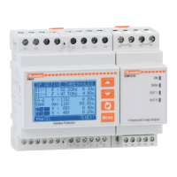
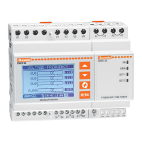
Modular construction for DIN rail, 6 units.

Display and Controls

LCD graphic 128x80 pixel, backlit, 4 grey levels. Display and setting buttons.

Voltage Input Configurations

Voltage measuring inputs three-phase + neutral. Possibility of operation in the following line configurations.

Relay Outputs

2 switching relay outputs to control: OUT1: IS (Interface Switch) coil control; OUT2: backup device control.

Digital Inputs

4 contact digital inputs for: INP1: IS feedback input; INP2: R.O.C.O.F and Vector Shift monitoring function inhibition.

Optional Measurements

Optional additional measurements, via connection of external CTs: Currents; Powers; Energies supplied.

Trip Thresholds Configuration

Voltage Thresholds

The voltage and frequency trip thresholds for which the equipment is set up according to the factory defaults are listed below.

Frequency Thresholds

PMVF 80 can be set to P≤50kW or P>50kW cases by specific commands available in the command menu.

Loss of Mains Detection

Loss of mains thresholds (islanding detection): R.O.C.O.F (rate of change of frequency) Vector shift.

Front Button Operations

MENU Button

Used to enter or exit the various display and setup menus.

Scroll Buttons (▲/▼)

Used to scroll between screens, select from available options and change settings.

Confirm/Select Button (SEL)

Used to scroll sub-pages, confirm selected options and switch between display modes.

Measurement Display Modes

Page Navigation

The ▲ and ▼ buttons allow measurement display pages to be scrolled one at a time.

Main Display Page

The first page displayed contains most important information in numerical and graphical form.

System Status Overview

The next page displays an overview of the state of the Interface Protection System, showing outputs and control inputs.

Trip Protection Counters

Three pages with trip protection counters follow, divided into total, voltage, and frequency trip counts.

Display Page Navigation and Sub-Pages

Sub-Page Access

The button permits access to sub-pages (e.g., to display maximum and minimum values).

Sub-Page Indicators

The sub-page is indicated by icons: IN, HI, AV, LO, GR.

Automatic Return Settings

Specify page and sub-page for automatic return after inactivity.

Display Persistence

Program PMVF 80 so the display always remains on the last selected page.

Main Menu Navigation

Menu Structure

The main menu consists of graphic icons for rapid access to measurements and settings.

Activating Menu Functions

Press MENU, select function with ▲/▼, press to activate.

Navigation Shortcuts

Operate as shortcuts for quicker access to measurement pages or selected groups.

Password Protected Access

Default Passwords

Default passwords: 1000 (user access) and 2000 (advanced access).

Access Levels

Two access levels: User-level access and Advanced-level access.

Entering Password

Press MENU, select password icon, enter password, press ✓.

Password Expiry

Access remains enabled until disconnection, reset, or 2 minutes of inactivity.

Setting Parameters (Setup)

Accessing Setup Menu

Press MENU, select icon, press to access the Setting Parameters (setup) menu.

Sub-Menu Selection

Use ▲/▼ to select desired menu, press to confirm.

Parameter Grouping

Sub-menus: M01 GENERAL, M02 UTILITY, M03 PASSWORD, M04 IP THRESHOLDS, M05 COMMUNICATION, M06 ALARMS.

General System Specifications (M01)

Rated Voltage Setting

P01.01 Rated voltage: set VLN or VLL based on connection type P01.06.

VT and CT Settings

P01.02/P01.03 VT primary/secondary voltage. P01.04/P01.05 CT primary/secondary current.

Connection and Control

P01.06 Voltage connection/control: specifies system configuration.

System Power

P01.07 Rated system power: AUT calculation or manual input.

LSP Control Output

P01.09 LSP protection control output selection: OUT1, OUT3, or both.

Utility Settings (M02)

Language Selection

P02.01 Language: Select between English and Italian.

Display Settings

P02.02-P02.05: Control LCD contrast and backlight intensity/delay.

Default Page Settings

P02.06/P02.07: Configure default page return and initial display page.

Default Sub-Page

P02.08: Set the default sub-page for display return.

Password Management (M03)

Enable Passwords

P03.01: Enable or disable password protection.

User Password

P03.02: Set the user-level access password.

Advanced Password

P03.03: Set the advanced-level access password.

IP Thresholds Configuration (M04)

Voltage Thresholds

P04.01-P04.04: Configure voltage trip thresholds (Umax, Umin).

Frequency Thresholds

P04.09-P04.12: Configure frequency trip thresholds (Fmax, Fmin).

R.O.C.O.F. and Vector Shift

P04.21/P04.23: Set R.O.C.O.F. and Vector Shift trip thresholds.

Delay Times

P04.05-P04.08: Define delay times for voltage threshold trips.

Communication Settings (M05)

Serial Communication

P05.1.01-P05.1.05: Configure serial node address, speed, data format, stop bits, and protocol.

TCP/IP Configuration

P05.1.06-P05.1.08: Set IP address, subnet mask, and IP port for Ethernet interface.

Gateway Function

P05.1.09: Enable or disable the gateway function.

Alarm Configuration (M06)

Alarm Enable/Disable

P06.01-P06.06: Enable or disable specific alarms (A01-A06).

Feedback Contact Use

Recommendation for using auxiliary feedback contact for IS, even if backup is not used.

Commands Menu Operations

Reset Functions

C.01-C.03: Reset measurements, trip counters, and partial energy meters.

Factory Defaults

C.12/C.13: Restore settings to factory defaults for P≤50kW or P>50kW.

Settings Backup/Restore

C.14/C.15: Save and reload device settings backup copy.

Threshold Inhibition

C.16/C.17: Temporarily disable voltage thresholds U> and U<.

Event Log Reset

C.18: Reset the event log.

Alarm Indications and Event List

IS Opening Failure (A02)

IP command to IS for opening, but auxiliary contact remains closed.

IS Closing Failure (A03)

IP command to IS for closing, but IS does not close or feedback contact fails.

HW Configuration Error (A04)

PMVF 80 did not find required expansion modules.

LSP Trip Indications (A05/A06)

Power Imbalance Limit protection LSP1 or LSP2 has tripped.

Event List Details

Event list provides description, time elapsed since power on, and total power on count.

Self-Diagnosis Function

System Error Codes

Self-diagnosis checks display 'System Error Exx' for malfunctions.

Error Reporting Procedure

Contact Technical Support and state the indicated error code for assistance.

Current, Power, and Energy Measurements

Measurement Enablement

Measures currents, powers, energies when CTs are connected and enabled via P01.04.

Exported/Imported Power Display

Active power produced (exported) shown with a minus sign, e.g. -6.5kW.

Trend Graph

Displays energy production trends over the last 24 hours.

Power Unbalance Limit (LSP) Control

LSP Functionality

Carries out Power Unbalance Limit function for three-phase+neutral systems with CTs.

LSP Trip Conditions

Trips on phase active power unbalance > 6kW for >30min or >10kW for >1min.

LSP Output Options

Programmable to open relay OUT3 or IS via OUT1, using parameters P01.09-P01.14.

LSP Trip Indication

Tripping highlighted by A05 and A06 alarms on the display.

LSP Restoration

Manual restoration by ▲ buttons or automatic restoration via P01.14.

Communication Module Options

Module Compatibility

PMVF 80 supports optional standard communication modules.

Module Configuration

Modules require configuration via the M05 - COMMUNICATION MENU.

Supported Protocols

Supports Modbus RTU, ASCII, and TCP variants.

Wiring Diagrams and Fuses

Three-Phase Connection Diagram

Illustrates the three-phase connection for the PMVF 80.

Low Voltage Distribution

Shows connection to the Low Voltage Distribution Network (L1, L2, L3, N).

Recommended Fuses

Specifies recommended fuses for auxiliary supply and contactor control.

Terminal Connection Notes

Details terminal connections for S2 and auxiliary IS feedback.

Backup Activation Modes

Mode Definitions

Default mode is A. Mode D mirrors the IS output.

Parameter Reference

See parameter P01.16 (M01 - GENERAL MENU) for configuration.

Terminal Layout and Dimensions

Terminal Layout

Diagram showing the layout of all device terminals.

Mechanical Dimensions

Provides detailed mechanical dimensions of the unit in millimeters.

Mounting and Device Symbols

Mounting Instruction

Procedure for mounting the device onto a DIN rail or surface.

Demounting Instruction

Procedure for removing the device from its mounting.

Device Symbols

Explains warning symbols and waste disposal icons.

Technical Characteristics

Auxiliary Supply Specs

Details rated voltage, operating range, frequency, and power consumption.

Voltmeter Input Specs

Covers max voltage, measuring range, frequency, measurement type, and connection.

Ammeter Input Specs

Details rated current, measuring range, input type, overload capacity, and burden.

Relay Output Specs

Specifies number of outputs, type, voltage, endurance, and mechanical life.

Digital Input Specs

Lists number of inputs, type, voltage levels, and input current.

Ambient Conditions

Details operating temperature, storage, humidity, pollution, pressure, and altitude.

Related product manuals