I681 GB 12 23 31100514
2
INTRODUCTION
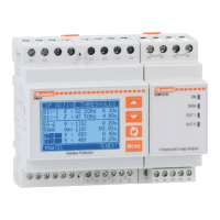
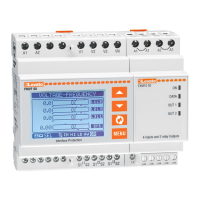
The PMVF52 equipment has been designed as an Interface Protection System (SPI) in accordance with the CEI 0-21 standard.
It can be applied to all LV micro-generation systems (photovoltaic, wind) where it is used to control the Interface Switch (IS) between generation system and public grid.
In the event of problems on the grid (e.g. due to maintenance), the system intervenes in a timely fashion, opening the Interface Switch (e.g. contactor) and isolating the generation system.
In the event of Interface Switch (IS) failure, it can also control a backup device to disconnect the generation system in any case.
The equipment features 5 digital inputs permitting the connection of the system to the signals provided by the network operator to meet the requirements of the current regulations.
The functions implemented and the possibility of further expansion ensure that it is prepared for any developments to the protection system.
The PMVF52 equipment is supplied already programmed and assembled. With the factory settings, once the connections have been made, it is already ready for operation in compliance with the requirements of the
CEI without requiring any further settings to be made. It is nevertheless prepared for any future changes to the operating parameters. Changes to the settings are password protected, preventing tampering by
unauthorised personnel.
DESCRIPTION
– Modular construction for DIN rail, 4 units.
– LCD graphic 128x80 pixel, backlit, 4 grey levels.
– 4 display and setting buttons.
– Voltage measuring inputs three-phase + neutral.
– Possibility of operation in the following line configurations:
•
three-phase with neutral, VL-L voltage controls (default)
•
three-phase with neutral, VL-N voltage controls
•
three-phase without neutral, VL-L voltage controls
•
single-phase, VL-N voltage control.
– 2 switching-relay outputs and 1NO output (OUT3) to control:
•
OUT1: IS (Interface Switch) coil control
•
OUT2: Backup device control
•
OUT3: Global alarm (programmable).
– 5 contact digital inputs for:
•
INP1: IS feedback input (auxiliary closure indication contact)
•
INP2: local control input
•
INP3: remote frequency threshold selection input (external signal)
•
INP4: remote tripping control input
•
INP5: programmable (default OFF).
– Settings lock via 2-level changeable password.
– Setup for future installation of IEC/EN/BS 61850 interface module.
– Possibility to have 2 multifunction programmable outputs (OUT4 and OUT5) and 2 multifunction programmable inputs (INP6 and INP7) on additional EXM1001 expansion module.
TRIP THRESHOLDS
– Below are the voltage and frequency trip thresholds for which the equipment is Setup according to the factory defaults, which correspond to the default requirements of the CEI 0-21 standard.
CONTENTS Page
Introduction . . . . . . . . . . . . . . . . . . . . . . . . . . . . . . . . . . . . . . . . . . . . . . . . . . . . . . . . . . . . . . . . . . . . 2
Description . . . . . . . . . . . . . . . . . . . . . . . . . . . . . . . . . . . . . . . . . . . . . . . . . . . . . . . . . . . . . . . . . . . . . 2
Trip thresholds . . . . . . . . . . . . . . . . . . . . . . . . . . . . . . . . . . . . . . . . . . . . . . . . . . . . . . . . . . . . . . . . . . 2
Front button functions . . . . . . . . . . . . . . . . . . . . . . . . . . . . . . . . . . . . . . . . . . . . . . . . . . . . . . . . . . . . 3
Displaying measurements . . . . . . . . . . . . . . . . . . . . . . . . . . . . . . . . . . . . . . . . . . . . . . . . . . . . . . . . . . 3
Table of display pages . . . . . . . . . . . . . . . . . . . . . . . . . . . . . . . . . . . . . . . . . . . . . . . . . . . . . . . . . . . . . 4
Main Menu . . . . . . . . . . . . . . . . . . . . . . . . . . . . . . . . . . . . . . . . . . . . . . . . . . . . . . . . . . . . . . . . . . . . . 4
Password-protected access . . . . . . . . . . . . . . . . . . . . . . . . . . . . . . . . . . . . . . . . . . . . . . . . . . . . . . . . 5
Setting parameters (Setup) . . . . . . . . . . . . . . . . . . . . . . . . . . . . . . . . . . . . . . . . . . . . . . . . . . . . . . . . . 5
Parameter table . . . . . . . . . . . . . . . . . . . . . . . . . . . . . . . . . . . . . . . . . . . . . . . . . . . . . . . . . . . . . . . . . . 6
Page
Commands Menu . . . . . . . . . . . . . . . . . . . . . . . . . . . . . . . . . . . . . . . . . . . . . . . . . . . . . . . . . . . . . . . . 8
Alarm indications . . . . . . . . . . . . . . . . . . . . . . . . . . . . . . . . . . . . . . . . . . . . . . . . . . . . . . . . . . . . . . . . 9
Self-diagnosis . . . . . . . . . . . . . . . . . . . . . . . . . . . . . . . . . . . . . . . . . . . . . . . . . . . . . . . . . . . . . . . . . . . 9
Communication . . . . . . . . . . . . . . . . . . . . . . . . . . . . . . . . . . . . . . . . . . . . . . . . . . . . . . . . . . . . . . . . . . 9
Wiring diagrams . . . . . . . . . . . . . . . . . . . . . . . . . . . . . . . . . . . . . . . . . . . . . . . . . . . . . . . . . . . . . . . . . 10
Backup activation modes . . . . . . . . . . . . . . . . . . . . . . . . . . . . . . . . . . . . . . . . . . . . . . . . . . . . . . . . . . 11
Terminal layout . . . . . . . . . . . . . . . . . . . . . . . . . . . . . . . . . . . . . . . . . . . . . . . . . . . . . . . . . . . . . . . . . . 11
Mechanical dimensions . . . . . . . . . . . . . . . . . . . . . . . . . . . . . . . . . . . . . . . . . . . . . . . . . . . . . . . . . . . . 11
Technical characteristics . . . . . . . . . . . . . . . . . . . . . . . . . . . . . . . . . . . . . . . . . . . . . . . . . . . . . . . . . . . 12
Voltage measurement type Voltage threshold Default Type Trip Trip delay Default
INSTANTANEOUS V > 59.S2 V > 115% MAX YES DEL 59.S2 0.20s
MOVING AVERAGE 10min Vmed > 59.S1 Vmed > 110% MAX YES DEL 59.S1 3.00s
INSTANTANEOUS 27.S1 <= V <= 59.S1 85% <= V <= 110% OK NO -- --
INSTANTANEOUS 27.S2 <= V < 27.S1 15% <= V < 85% MIN YES DEL 27.S1 1.50s
INSTANTANEOUS V < 27.S2 V < 15% MIN YES DEL 27.S2 0.20s
External Local Control MIN F Default MIN F Default MAX F Default MAX F Default
signal threshold delay threshold delay
ON OFF 81<.S2 47.50Hz DEL C MIN F 0.10s 81>.S2 51.50Hz DEL C MAX F 0.10s
OFF ON 81<.S2 47.50Hz DEL L MIN F 4.00s 81>.S2 51.50Hz DEL L MAX F 1.00s
ON ON 81<.S1 49.80Hz DEL C MIN F 0.10s 81>.S1 50.20Hz DEL C MAX F 0.10s
– The frequency thresholds and corresponding delays may vary in accordance with the state of the input signals named Local Control and External Signal.
– A condition with both signals OFF is not envisaged/defined. Should it occur, the equipment will provide an alarm indication.
– The table indicating trip thresholds and times in the conditions envisaged follows:
 Loading...