p. 1 / 25
RGK 50 RGK 50
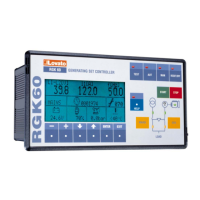
Панель управления Gen-set control
RGK 60 RGK 60
Панель управления Gen-set control
с автоматическим контролем
сети with Automatic Mains Failure
РУКОВОДСТВО ПО ЭКСПЛУАТАЦИИ INSTRUCTIONS MANUAL
Введение
При разработке описываемого устройства управления генераторной
установкой была поставлена цель максимально упростить работу с
прибором и уйти от постоянного обращения оператора к
справочному руководству, для чего в программное меню прибора
введена встроенная справочная система. Для большинства
используемых функций прибора (установки параметров, индикации
параметров, аварийных сообщений системы) доступно получение
справки от встроенной справочной системы. Доступность получения
справочной информации индицируется свечением светодиода на
клавише HELP. Исходя из вышесказанного, в данном руководстве
содержится только наиболее существенная информация, такая как
таблица аварийных сообщений, детальное описание режимов
работы прибора, таблица параметров, список функций прибора и
технические характеристики.
Introduction
This device has been designed to facilitate the use by the gen-set
operator, by avoiding the continuous need to consult the instructions
manual. In most utilisation circumstances, for instance parameter
setting, data display, alarm conditions, etc., the LED on the HELP key
is switched on when a help message is available for consulting.
Therefore, this manual contains essential information, such as details
for the operator for the RGK use, alarms table, parameters tables,
functions list and technical characteristics.
Клавиатура
HELP клавиша – В случае, если клавиша подсвечена светодиодом,
возможен доступ к получению справочной информации по текущей
выполняемой операции устройства.
Доступ к справке осуществляется нажатием клавиши.
ENTER и EXIT клавиши – Нажатием клавиши ENTER производится
вход в меню прибора или выбор операции. Нажатие клавиши EXIT
ведет к отказу от выполнения операции, а также к выходу из меню
или справочной системы.
“” и “” клавиши–стрелки служат для выбора страницы
отображения данных или выбора необходимого параметра.
“+” и “-“ клавиши служат для выбора индикации альтернативных
параметров или же для модификации значения параметра.
START и STOP клавиши предназначены для управления запуском и
остановкой двигателя в ручном режиме работы устройства
управления генераторной установкой (режим MAN).
Кратковременное нажатие клавиши START приводит к выполнению
одной попытки запуска двигателя. Время выполнения попытки
старта может быть увеличено посредством удержания клавиши
START нажатой. Мигание светодиода расположенного под символом
двигателя на мнемосхеме означает, что двигатель запущен, но
контроль аварийных сообщений (алармов) блокирован. После
истечения времени блокировки аварийных сообщений свечение
светодиода переходит в постоянное. Остановка двигателя
происходит по нажатию клавиши OFF/RESET.
Keyboard
HELP key – The illuminated LED means a help message is available.
By pressing the key, a help message concerning the current operation
is displayed.
ENTER and EXIT keys - Press ENTER to confirm operations or to
enter the menu. Press EXIT to refuse an operation or to exit a menu
and help message.
“” and “” arrow keys – Press these keys to shift to the different
pages of data display or to select parameters.
“–“ and “+” keys Press these keys to display other data of the
selected data page or to modify the parameters.
OFF/RESET, MAN, AUT and TEST keys – Press these keys to select
the operating mode. The illuminated LED indicates the selected
operating mode; if it is flashing, remote control is active.
START and STOP keys – These work in MAN operating mode only,
used to start and stop the engine. By quickly pressing the START key,
one start attempt takes place; by keeping the START key pressed, the
duration of the start attempts can be extended. The flashing LED of
the engine symbol denotes engine started, with alarms inhibited; and
is constantly on at the end of the alarms inhibition time. The engine
can be stopped using the OFF/RESET key.
MAINS и GEN клавиши RGK 60 предназначены для переключения
питания потребителя от внешней сети на генератор или наоборот.
Эти клавиши действуют только при выборе ручного режима работы
устройства. Свечение светодиодов расположенных под символами
MAINS and GEN keys RGK 60 – They work in MAN operating
mode only, used to switch the load from mains to generator and
vice versa. The illuminated LEDs of the mains and generator
symbols indicate the respective voltages are within preset limits.
WARNING! This equipment is to be installed by qualified
personnel, complying to current standards, to avoid damages
or safety hazards. Products illustrated herein are subject to
alteration and changes without prior notice. Technical data
and descriptions in the documentation are accurate, to the
best of our knowledge, but no liabilities for errors, omissions
or contingencies arising therefrom are accepted.
Внимание!Технические описания и данные,
приведенные в данном руководстве, являются
наиболее полными на данный момент, но могут быть
изменены без предупреждения, и возможно могут
содержать ошибки. Кроме того, подразумевается, что
установка прибора производится специально
обученным персоналом, и в полном соответствии с
требованиям существующих стандартов и нормативов
во избежание несчастных случаев.