Do you have a question about the LOVATO ELECTRIC VLA1 series and is the answer not in the manual?
Configures the run/stop command using a 2-wire control from the flexible I/O terminal block.
Sets up the run/stop command functionality via the device keypad.
Adjusts the output frequency using the device's keypad interface.
Sets frequency adjustment using an external potentiometer connected to analog input 1.
Configures frequency adjustment using a 0-10V analog input signal.
Sets frequency adjustment using a 4-20mA analog input signal.
Configures frequency adjustment using predefined setpoints activated by digital inputs.
Enables frequency adjustment using dedicated MOP UP/DOWN inputs.
Configures PID control with keypad setpoint and 0-10V feedback signal.
Configures PID control with keypad setpoint and 4-20mA feedback signal.
Enables automatic identification of motor data for optimal parameter settings.
Configures the function of the relay output with changeover contact.
Configures the function of the digital output (DO1).
Sets the parameters for the A01 analog output function.
Enables the automatic start of the motor after power-up.
Details how to command digital inputs from a PLC.
Switches between automatic PID control and manual frequency regulation using digital inputs.
Configures manual frequency regulation via a potentiometer for MAN mode.
Sets PID control parameters for automatic (AUT) mode.
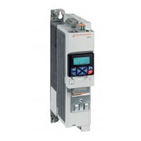
The Lovato Electric VLA1 is a variable speed drive designed for precise motor control in various industrial applications. This quick guide outlines the essential steps for configuring the drive, from basic navigation to advanced functions and troubleshooting.
The VLA1 drive allows users to control the speed and operation of a motor by adjusting its output frequency. It supports several control modes, including V/f characteristic control (open loop) for general applications like conveyor belts and pumps/fans, and sensorless vector control for more demanding tasks. The drive can be commanded to run and stop the motor through various interfaces, such as a flexible I/O terminal block or the integrated keypad.
Frequency adjustment, a core function, can be achieved through multiple methods. Users can set the frequency directly from the keypad, use an external potentiometer, or provide an analog input signal (0-10V or 4-20mA). For applications requiring specific speeds, the VLA1 supports preset frequency setpoints, allowing for quick selection of predefined operating speeds. Additionally, a motor potentiometer (MOP) function enables incremental adjustment of the frequency setpoint via dedicated input contacts.
The VLA1 also integrates a Proportional-Integral-Derivative (PID) control function, which is crucial for maintaining a desired process variable (e.g., pressure, flow) by automatically adjusting the motor's speed. The PID setpoint can be adjusted via the keypad, and feedback can be provided through analog inputs. The PID function includes a sleep mode that activates when the frequency falls below a set threshold for a specified duration, optimizing energy consumption.
For enhanced automation and integration, the drive offers configurable digital and analog output functions. A relay output can be configured to signal various operational states, such as "running," "error active," "frequency threshold exceeded," or "current limit reached." Similarly, a digital output (DO1) can provide status indications for these same conditions. An analog output (A01) can be configured to represent actual output frequency, frequency setpoint, input signal values, motor current, output power, or torque, allowing for real-time monitoring and integration with external control systems.
The VLA1 supports an auto-restart function, enabling the motor to automatically restart after a power-up event, provided certain safety requirements are met and the drive is properly enabled. This feature is particularly useful in applications where continuous operation is critical. The drive can also be controlled by a PLC, with options for dry contact, PNP, or tensioned output connections for digital inputs, facilitating seamless integration into larger automation architectures.
Navigating the VLA1's menu is intuitive, with dedicated keypad keys for selecting groups, parameters, and modifying settings. A short press allows entry into sub-parameter levels, while a long press (over 3 seconds) saves parameter settings to memory. The keypad also provides direct controls for stopping and running the motor, activating full keypad control, and reversing the direction of rotation.
The drive's configuration process is structured logically, starting with basic setup like resetting parameters to default, defining run/stop commands, and selecting frequency adjustment methods. Users then proceed to set motor-specific parameters, which can be further optimized through an automatic motor data identification procedure. This procedure, performed when the motor is cold and stopped, automatically identifies the motor's characteristics to achieve optimal performance.
The VLA1's flexible I/O terminal block allows for versatile wiring configurations, accommodating various sensors, potentiometers, and control signals. The ability to configure digital inputs for switching between automatic (PID) and manual (frequency regulation) modes provides operational flexibility, allowing users to choose the most suitable control strategy for their application. For instance, in manual mode, the PID control is deactivated, and the frequency is regulated via an external potentiometer.
The VLA1 includes several features to aid in maintenance and troubleshooting. The automatic motor data identification process, for example, helps ensure that the drive operates with the most accurate motor parameters, reducing the likelihood of performance issues or premature wear.
The drive provides a comprehensive list of common error codes, each with possible causes and recommended remedies. These error codes cover a range of issues, including motor overload, short circuit/earth leakage, I*t errors, DC bus over/undervoltage, and power unit overtemperature. For instance, a motor overload error (0x2350) might indicate impermissible continuous current or too frequent acceleration processes, with remedies suggesting a check of drive dimensioning or machine/driven mechanics.
For power unit overtemperature errors (0x4210), the drive's diagnostic capabilities point to potential causes such as high ambient temperature, polluted fan/ventilation slots, or a defective fan. Recommended remedies include ensuring sufficient cooling, cleaning the fan and ventilation slots, replacing the fan if necessary, or reducing the switching frequency. This detailed error reporting and troubleshooting guide empower users to quickly diagnose and resolve issues, minimizing downtime and extending the lifespan of both the drive and the motor.
| Series | VLA1 |
|---|---|
| Control Mode | PWM |
| Type | DC Drives |
| Protection | Overcurrent, Overtemperature |
| Humidity | 5-95% non-condensing |