EasyManua.ls Logo

Love Controls C Series - User Manual

Default Icon
7 pages
Print Icon
To Next Page IconTo Next Page
Loading...
5011643800-DWC0
2006-02-15
C Series Temperature Controller
Instruction Sheet
Thank you very much for purchasing a Love Controls Series C Temperature Controller. Please read this instruction sheet before using
your controller to ensure proper operation and please keep this instruction sheet handy for quick reference.
1 Precaution
DANGER! Caution! Electric Shock!
1. Do not touch the AC terminals while the power is supplied to the controller to prevent an electric shock.
2. Make sure power is disconnected while checking the unit inside.
3. The symbol
indicates this Controller is protected throughout by DOUBLE INSULATION or REINFORCED INSULATION
(equivalent to Class II of IEC 536).
WARNING!
Mount the controller in a location that will not be subject to excessive temperature, shock, or vibration. All models are designed for
mounting in an enclosed panel..
1. Always use recommended solder-less terminals: Fork terminal with isolation (M3 screw, width is 7.0mm, hole diameter 3.2mm).
Screw size: M3 x 6.5 (With 6.8 x 6.8 square washer). Recommended tightening torque: 0.4 N.m (4kgf.cm). Applicable wire:
Solid/twisted wire of 2 mm
2
, 12AWG to 24AWG. Please be sure to tighten them properly.
2. Do not allow dust or foreign objects to fall inside the controller to prevent it from malfunctioning.
3. Never modify or disassemble the controller.
4. Do not connect anything to the “Not used” terminals.
5. Make sure all wires are connected to the correct polarity of terminals.
6. Do not install and/or use the controller in places subject to: Dust or corrosive gases and liquid, high humidity and high radiation,
vibration and shock, high voltage and high frequency
7. Power must be off when wiring and changing a temperature sensor.
8. Be sure to use compensating wires that match the thermocouple types when extending or connecting the thermocouple wires.
9. Please use wires with resistance when extending or connecting a platinum resistance sensor (RTD).
10. Please keep the wire as short as possible when wiring a platinum resistance sensor (RTD) to the controller and please route
power wires as far as possible from load wires to prevent interference and induced noise.
11. This controller is an open-type unit and must be placed in an enclosure away from high temperature, humidity, dripping water,
corrosive materials, airborne dust and electric shock or vibration.
12. Please make sure power cables and signals from instruments are all installed properly before energizing the controller, otherwise
serious damage may occur.
13. Please do not touch the terminals in the controller or try to repair the controller when power is applied to prevent an electric
shock.
14. Wait at least one minute after power is disconnected to allow capacitors to discharge, and please do not touch any internal circuit
within this period.
15. Do not use acid or alkaline liquids for cleaning. Please use a soft, dry cloth to clean the controller.
16. This instrument is not furnished with a power switch or fuse. Therefore, if a fuse or power switch is required, install the protection
close to the instrument. Recommended fuse rating: Rated voltage 250 V, Rated current 1 A. Fuse type: Time-lag fuse
17. Note: This controller does not provide overcurrent protection. Use of this product requires that suitable overcurrent protection
device(s) must be added to ensure compliance with all relevant electrical standards and codes. (Rated 250 V, 15 Amps max). A
suitable disconnecting device should be provided near the controller in the end-use installation.
2 Display, LED, and Pushbuttons
Bulletin E-90-C
PV displays process value
SV displays setpoint value.
INDEX: advances the display to the next menu item.
UP ARROW: Increments a value or changes a menu item.
DOWN ARROW: Increments a value or changes a menu item.
ENTER: stores the value or item change.
Question and Answer IconNeed help?

Do you have a question about the Love Controls C Series and is the answer not in the manual?

Summary

Safety and Warnings

Electric Shock Safety Precautions

Important safety precautions regarding electric shock hazards.

Installation and Environment Warnings

Precautions for mounting and installing the controller to prevent damage or hazards.

User Interface Description

Display, LED, and Pushbutton Functions

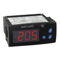
Description of the controller's display, LEDs, and pushbuttons for operation.

Sensor and Operation Setup

Sensor Type and Temperature Range

Details sensor types compatible with the controller and their respective temperature ranges.

Operation Modes Overview

Overview of the controller's operation modes: operation, regulation, and initial setting.

Setting Temperature Setpoint

Instructions on how to set the temperature set point using the controller's buttons.

Regulation Mode Settings

Configuration options available in the Regulation Mode, including auto-tuning and PID parameters.

Initial Setting Mode Configuration

Configuration options for initial setup, including input type, units, and control method.

Parameter Configuration Details

Initial Setting Mode Parameters

Additional parameters for initial setup, covering control cycles and deviation value regulation.

Operation Mode Parameters List

List of parameters relevant to the controller's operation mode, including RUN/STOP and lock functions.

Regulation Mode Control Parameters

Detailed list of control parameters for PID and ON/OFF control modes.

Advanced Settings and Alarm Functions

Initial Setting Mode Options

Options for initial setup: sensor input, engineering units, control method, and action.

Program Execution Control

Procedure for executing programmed settings and stopping control output.

Heating and Cooling Operation

Instructions for configuring the controller for heating or cooling operations.

Input Error and Range Indication

Indicates how input errors and measured value exceeding range are displayed.

Alarm Output Configuration

Details alarm types, their configurations, and output operations based on PV and set values.

Alarm Operations and Specifications

Alarm Output Types and Operations

Comprehensive list of alarm types, including deviation, absolute, and hysteresis alarms, with their operational logic.

Controller Technical Specifications

Technical specifications of the controller, including input voltage, power, sensor types, and environmental ratings.

Physical Dimensions and Wiring

Panel Cutout Dimensions

Required panel cutout dimensions for mounting the controller models.

Terminal Identification and Wiring

Diagram and identification of all terminal connections for wiring the controller.

Mounting and External Dimensions

External Dimensions Overview

Overall external dimensions of the 16C, 8C, and 4C controller models.

Mounting Method Instructions

Step-by-step instructions for securely mounting the controller in a panel.

Love Controls C Series Specifications

General IconGeneral
Input TypesThermocouple, RTD
Output TypesRelay
Control ModesOn/Off, PID
DisplayLED
Power Supply24 VAC/VDC
CommunicationRS-485 Modbus
Enclosure RatingNEMA 4X

Related product manuals