EasyManua.ls Logo

LS ELECTRIC iX7NH Series - User Manual

LS ELECTRIC iX7NH Series
38 pages
Print Icon
To Next Page IconTo Next Page
Loading...
iX7NH Series AC Servo Drive
Quick Start Guide


This QuickStart Guide is designed to get an iX7NH servo system installed and running quickly.
This AutomationDirect Guide is a supplement to the LS Electric iX7NH User Manual. This Guide
does not replace the manufacturer’s User Manual. For advanced features or options required
by your application, you may still need to refer to the User Manual. Download and reference
both this QuickStart Guide and the iX7NH User Manual when commissioning an iX7NH servo
system.
This quickstart guide will get your iX7NH drive configured and commissioned using Drive CM.
This is helpful for:
For further EtherCAT commissioning help, see AutomationDirect’s LS Electric Interactive PLC
Guide available at https://cdn.automationdirect.com/static/helpfiles/ls_plc/Content/Home.htm
For further Modbus TCP commissioning, see the iX7NH Modbus TCP Communications Guide.
A note on Part Numbers: LS Electric servo parts sold by AutomationDirect have part numbers
that end with “-AD”. This suffix signifies special packaging and labeling for AutomationDirect.
All the LS servo products with the “-AD” function and behave exactly the same as the standard
LS Electric parts. Please note that when reading the LS electric User Manual or using the Drive
CM software, the “-AD” will NOT appear in any part numbers. For example, AutomationDirect
part iX7NHA004U-AD is just iX7NHA004U in the LS Electric documentation.
NOTE: EtherCAT® is a registered trademark and patented technology, licensed by Beckhoff
Automation GmbH, Germany.
Modbus TCP
Question and Answer IconNeed help?

Do you have a question about the LS ELECTRIC iX7NH Series and is the answer not in the manual?

Overview

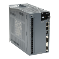
The document describes the LS Electric iX7NH Series AC Servo Drive, a component designed for precise motion control in industrial applications. This Quick Start Guide serves as a supplement to the manufacturer's User Manual, focusing on rapid installation and commissioning using the Drive CM software. The iX7NH servo system supports both EtherCAT and Modbus TCP communication protocols.

Function Description

The iX7NH servo drive controls compatible LS Electric APM/APMC servo motors, enabling precise position, velocity, and torque control. It integrates with a PC via USB for configuration using the Drive CM software, and can be controlled by EtherCAT or Modbus TCP controllers. The drive features digital inputs and outputs for various control signals, analog inputs for torque limiting, and analog outputs for monitoring. Safety functions, such as Safe Torque Off (STO), are built-in to meet safety standards.

Important Technical Specifications

Drive Specifications:

  • Input Voltage: 115V/230V AC (single-phase) or 230V AC (three-phase), depending on power rating.
  • Power Ratings: Available from 100W to 3.5 kW.
    • 400W drives: 1-phase 115V/230V, 3-phase 230V.
    • 750W - 2.2 kW drives: 1-phase (with derating) or 3-phase 230V.
    • 3.5 kW drives: 3-phase 230V only.
  • Motor Torque Derating (Single-phase usage):
    • 100W/200W/400W: Single-phase and three-phase input both produce 300% max torque.
    • 750W: Single-phase and three-phase input both produce 300% max torque.
    • 1kW: 2kW drive produces 300% max torque. 1kW drive can be used, but motor provides 200% max torque.
    • 1.5kW/1.6kW/2.2kW: 3.5kW drive produces 200% max torque with 1.5kW and 1.6kW motors. With single-phase supply, this drive only produces 150% max motor torque with a 2.2kW motor.
    • 3.5kW: No single-phase capability.
  • Communication Protocols: EtherCAT® (registered trademark of Beckhoff Automation GmbH) and Modbus TCP.
  • Node Address: Configurable via rotary dials (0-97 for EtherCAT, 98 or 99 for Modbus TCP). Node 99 enables a built-in webserver.
  • Safety Function: Safe Torque Off (STO) circuit meets Safety Category 3, Safety Integrity Level 2 (SIL 2), Performance Level d (PL d). STO rated voltage is 12VDC to 24VDC.
  • Digital Inputs/Outputs: Rated voltage 12VDC to 24VDC. Digital outputs are 24VDC ± 10% and 120mA.
  • Analog Input (Torque Limit): Range -10V to +10V, impedance approximately 10kΩ.
  • Analog Monitor Output: -10V to +10V.
  • Motor Encoder Resolution: 19-bit serial encoders (524288 pulses/revolution) for APM(C)-FxxxxAMK-AD motors.
  • Connectors: Main Power (L1, L2, L3), Control Power (C1, C2), Motor (U, V, W), Encoder, I/O, Safety (STO), Regenerative Resistor (B+, B, BI), DC Reactor (PO, PI), USB (Mini B Type), EtherCAT In/Out, Analog Monitor.

Motor Specifications (APMC and APM Servo Motors):

  • Frame Sizes: BL (62mm square), CL (80mm square), E (130mm square), F (180mm square).
  • Power: Indicated in hundreds of watts (YY).
  • Rated Speed: 3000rpm (A) or 2000rpm (D).
  • Brake: Indicated by "(2)" at the end of the part number for built-in brake.

Environmental Conditions:

  • Operating Temperature:
    • Servo Drive: 0-50°C [32-122°F] (requires cooling fan for ventilation).
    • Servo Motor: 0-40°C [32-104°F] (requires forced air cooling if motor temperature exceeds 40°C).
  • Operating Humidity:
    • Servo Drive: 90% relative humidity or below (non-condensing).
    • Servo Motor: 80% relative humidity or below (non-condensing).
  • External Vibration:
    • Servo Drive: 4.9 m/s² (0.5 G) or lower.
    • Servo Motor: 19.6 m/s² (2.0 G) or lower on X and Y axes.
  • Ambient Conditions: Free from direct sunlight, corrosive/combustible gases, oil, or dust. Sufficient ventilation required.

Usage Features

  • Quick Start Instructions: Provides a step-by-step guide for initial setup, including wiring, power-up, PC connection, Setup Wizard, fault clearing, and motor jogging.
  • Drive CM Software: A Windows-based application for configuration and commissioning.
    • Immediate Changes: Settings made in Drive CM take effect immediately in the drive without "Are you sure?" warnings. This allows for quick testing and troubleshooting.
    • Setup Wizard: Guides users through basic parameter settings for the system, including motor/encoder settings, rotation direction, electronic gear ratio, emergency stop, dynamic brake control, brake signal settings, torque limit function, and I/O signal settings.
    • Main and Auxiliary Windows: Drive CM features a larger Main Window for setup and configuration and a smaller Auxiliary Window for dynamic operations.
    • Toolbar Functions: Icons for Trace/Trigger Monitor, Cyclic Monitor, Motor Encoder Setup, General Configuration Setup, Fault Configuration, Controls Loop, Object Dictionary, PTP Move, Jog Manual, Torque Control, Homing, Tuning, Digital Input/Output, Analog Input/Output, Save to Drive Memory, Reset Servo Alarm, Software Reset for Drive CPU power cycle, Firmware Update, and Emergency STOP.
  • Pre-made Motor Cables: Available in normal and robotic flex specifications, in lengths from 3m to 20m, for all iX7NH drive and motor sizes.
  • I/O Configuration: Digital inputs and outputs are highly configurable, allowing assignment of 17 input functions and 11 output functions. Analog input can be used for torque limiting.
  • Modbus TCP Webserver: When Node ID DIP switches are set to 99, the drive generates a built-in webserver for configuration and commissioning (though Setup Wizard features are only available via Drive CM).
  • Electronic Gear Ratio: Allows users to define the number of user units per motor revolution, simplifying positioning commands (e.g., 360 user units for one motor revolution to represent degrees).
  • Analog Torque Limit: The drive accepts an analog -10V to +10V signal to limit motor output torque. AutomationDirect offers FA-DCDC-1 DC-to-DC converter and ECX2300-10K potentiometer for this purpose.

Maintenance Features

  • Periodic Inspections: Regular checks for securely tightened screws (drive, motor shaft, terminal blocks), prevention of contaminants (oil, water, metallic particles, dust, harmful gases), and protection of encoder cables from stress.
  • Pre-operation Inspections (Power OFF): Grounding terminal connection, isolation of wires, correct wiring, removal of conductive/flammable objects, emergency stop switch status, electromagnetic brake function, and external voltage level.
  • Pre-operation Inspections (Power ON): Checking for motor vibration/noise, correct parameter settings, resetting parameters when Servo OFF, and proper function of relays, power indicator, and LED display.
  • Alarms and Warnings: The LED display shows status, digital I/O states, alarms, and warnings. A comprehensive list of alarms (e.g., IPM fault, overcurrent, encoder errors, power issues) and warnings (e.g., phase loss, battery low voltage, overload) is provided, indicating whether an immediate reset or a power cycle/software reset is needed.
  • Software Reset: A software reset button in Drive CM allows for power cycling the CPU only, which is useful after writing settings that require a power cycle to take effect.
  • Firmware Update: Drive CM software supports firmware updates.
  • Shielding: APCS-L7NCN1Txxx-AD cables provide shielding between the servo and terminal blocks. User-provided shielding is recommended for high-speed and analog signals, grounded on the PLC side.
  • Regenerative Resistor: The drive supports internal or external regenerative resistors. External resistors can be connected by removing the internal jumper.

LS ELECTRIC iX7NH Series Specifications

General IconGeneral
BrandLS ELECTRIC
ModeliX7NH Series
CategoryServo Drives
LanguageEnglish